EasyManua.ls Logo

Panasonic CS-PE12DKE User Manual

Panasonic CS-PE12DKE
77 pages
To Next Page IconTo Next Page
Page #1 background imageLoading...
Page #1 background image
CS/CU-PE9DKE
CS/CU-PE12DKE
Air Conditioner
WARNING
This service information is designed for experienced repair technicians only and is not designed for use by the general public.
It does not contain warnings or cautions to advise non-techical individuals of potential dangers in attempting to service a product.
Products powered by electricity should be serviced or repaired only by experienced professional technicians. Any attempt to service
or repair the product or products dealt with in this service information by anyone else could result in serious injury or death.
1 Features 2
2 Functions 3
3 Product Specifications 6
4 Dimensions 10
5 Refrigeration Cycle Diagram 12
6 Block Diagram 13
7 Wiring Diagram 14
8 Operation Details 15
9
Installation instructions
41
10 Installation and Serving Air Conditioner Using R410A
11
Disassembly of The Parts
12 Troubleshooting Guide
13 Technical Data
14 Exploded View
15 Replacement Parts List
16 Exploded View
17 Replacement Parts List
18 Electronic Circuit Diagram
CONTENTS
Page Page
Order No.
Guangzhou Matsushita Air Conditioner Co., Ltd.
(GMAC) All rights reserved. Unauthorized copying
and distribution is violation of law.
C
R
50
62
65
67
68
69
70
71
72
------------------------------------------------------
--------------------------------------------------------
------------------------------------------
-----------------------------------------------------
-----------------------------------
--------------------------------------------------
-------------------------------------------------
-----------------------------------------------
---------------------------------------------------
--------------------------------------
----------------------------------------
--------------------------------------------------
--------------------------------------------------
-----------------------------------------
--------------------------------------------------
-----------------------------------------
--------------------------------------
R
GMAC0506048C3
hr
DELAY
hr
DELAY
OFF ON
SELECT
SET/C
ANCEL
ERROR RESET
ON
OFF
INVERTER
AUTO
HEAT
COOL
DRY
OFF
Question and Answer IconNeed help?

Do you have a question about the Panasonic CS-PE12DKE and is the answer not in the manual?

Panasonic CS-PE12DKE Specifications

General IconGeneral
Cooling Capacity3.5 kW
Energy Efficiency Ratio (EER)3.21
COP (Heating)3.61
RefrigerantR410A
Noise Level (Outdoor)50 dB
Indoor Unit Dimensions (W x H x D)870 x 290 x 204 mm
Outdoor Unit Dimensions (W x H x D)780 x 540 x 289 mm
Weight (Indoor Unit)9 kg
Weight (Outdoor Unit)30 kg
TypeSplit
Heating Capacity4.0 kW
EER (Cooling)3.21
Power Supply220-240 V, 50 Hz
Noise Level (Indoor)41 dB

Summary

Features

Functions

Remote Control Functions

Explains the functions and operation of the remote control for the air conditioner.

Product Specifications

Dimensions

Indoor Unit Dimensions

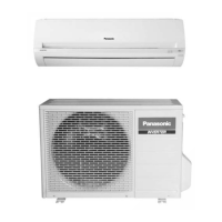
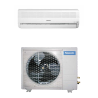
Provides detailed dimensions and diagrams for the indoor unit of the air conditioner.

Outdoor Unit Dimensions

Provides detailed dimensions and diagrams for the outdoor unit of the air conditioner.

Refrigeration Cycle Diagram

Block Diagram

Wiring Diagram

Operation Details

Operation and Display of Remote Controller

Details the functions, display, and operation modes of the air conditioner's remote controller.

Operation and Display of Indoor Unit

Explains the functions, indicators, and operational modes of the indoor unit of the air conditioner.

Cooling Operation

Anti-freezing Control

Describes the anti-freezing control mechanisms during cooling operation to prevent ice formation.

Anti-Fog Protection

Details protection measures against fogging during cooling operation.

Overload Protection For Cooling Operation

Explains the overload protection mechanisms implemented during cooling operation.

Soft Dry Operation

Thermostat Features

Outlines the thermostat features and temperature control logic for soft dry operation.

Indoor Fan Control for Soft Dry

Describes the indoor fan speed control strategy during soft dry operation.

Heating Operation

Indoor Fan Control for Heating

Explains how the indoor fan speed is controlled based on indoor piping temperature during heating operation.

Auto Fan Speed Control

Details the auto fan speed settings and logic during heating operation.

Overload Protection Control

Describes the overload protection mechanisms determined by indoor piping temperature during heating operation.

Outdoor Air Temperature Control

Explains the outdoor air temperature control logic for heating operation.

New JIS Deice Operation

Normal Deice Operation

Automatic Operation

Delayed ON-Timer Control

Auto Restart Control

Air Quality Sensor Control

Air Quality Monitoring and Indication

Explains how the air quality sensor detects and indicates air quality levels.

Forced Resetting Procedure

Describes the procedure for forced resetting of air quality sensor settings.

Timer Resetting Conditions

Explains the conditions under which the timer is reset based on air quality changes.

Added Operation Logic

Details the added operation logic when air quality changes, impacting unit performance.

Sensitivity Control of Air Quality Sensor

Guides on how to change the sensitivity settings of the air quality sensor.

Installation Instructions

Safety Precautions During Installation

Provides critical safety precautions to be followed before and during the installation of the air conditioner.

Selecting the Best Location

Offers guidance on selecting the optimal location for installing the indoor and outdoor units.

Indoor Unit Installation Procedures

Indoor Unit Location Selection

Specific guidance on selecting the best location for the indoor unit installation.

Fixing the Installation Plate

Step-by-step instructions on how to securely fix the installation plate for the indoor unit.

Drilling Wall Hole and Installing Piping Sleeve

Guides on drilling wall holes and installing piping sleeves for indoor unit connections.

Indoor Unit Installation Steps

General instructions for the installation of the indoor unit itself.

Connecting Cable to Indoor Unit

Details on connecting the electrical cable to the indoor unit.

Outdoor Unit Installation Procedures

Outdoor Unit Location Selection

Guidance on selecting the best location for the outdoor unit installation.

Outdoor Unit Installation Steps

Instructions for the physical installation of the outdoor unit.

Connecting Refrigerant Piping

Steps for connecting the refrigerant piping to the outdoor unit.

Equipment Evacuation Procedure

Procedures for evacuating the air from the indoor unit and piping systems.

Air Purging of Piping and Indoor Unit

Instructions for purging air from the refrigerant piping and indoor unit.

Connecting Cable to Outdoor Unit

Details on connecting the electrical cable to the outdoor unit.

Refrigerant Pipe Insulation

Guidance on insulating refrigerant piping to prevent condensation and heat loss.

Outdoor Unit Drain Water Management

Outdoor Unit Drain Water Disposal

Instructions on managing and disposing of drain water from the outdoor unit.

Drainage System Check

Procedures for checking the proper functioning of the drainage system.

Performance Evaluation

Methods for evaluating the performance of the air conditioner after installation.

Installation and Servicing with R410A

R410A Refrigerant Overview

Provides an overview and general information about installing and servicing air conditioners using R410A refrigerant.

R410A Refrigerant Characteristics

Discusses the characteristics, properties, and safety considerations of R410A refrigerant.

Safety Measures for Refrigerant Piping

Highlights essential safety measures for handling and installing refrigerant piping systems.

Tools for Refrigerant Piping Work

Necessary Tools List

Lists the essential tools required for the installation, transferring, and servicing of refrigerant piping.

Refrigerant Piping Work Procedures

Refrigerant Piping Materials

Specifies the recommended types and specifications for refrigerant piping materials used with R410A.

Processing and Connecting Piping Materials

Details the procedures and precautions for processing and connecting refrigerant piping materials.

Installation, Transferring, and Servicing

Inspecting Gas Leaks

Explains the process of inspecting for gas leaks using a vacuum pump after new refrigerant piping installation.

Transferring Unit with New Piping

Provides instructions for transferring the air conditioner unit with new refrigerant piping.

AC Unit Replacement with Existing Piping

Guides on replacing AC units, including considerations for existing refrigerant piping.

Refrigerant Compatibility (R410A vs R22)

Discusses refrigerant compatibility issues when mixing R410A and R22 systems.

Recharging Refrigerant During Servicing

Outlines the procedure for recharging refrigerant during servicing operations.

Brazing Procedures

Covers the techniques and precautions for brazing refrigerant piping connections.

Disassembly of Parts

Intake Grille Removal

Step-by-step guide on how to remove the intake grille from the indoor unit.

Front Grille Removal

Instructions for safely removing the front grille of the indoor unit.

Electronic Controller Removal

Details the steps for removing the electronic controller assembly from the indoor unit.

Discharge Grille Removal

Guides on how to remove the discharge grille from the indoor unit.

Cross Flow Fan Removal

Explains the process of removing the cross-flow fan from the indoor unit assembly.

Troubleshooting Guide

Refrigeration Cycle System Diagnosis

Guides on diagnosing refrigeration cycle issues by analyzing pressures and temperatures.

Pressure and Current Relationships

Illustrates the correlation between air conditioner conditions, pressure, and electric current.

Compressor Malfunction Diagnosis

Provides methods for diagnosing compressor malfunctions based on symptoms and electric current readings.

Technical Data

Operating Characteristics Charts

Presents operational characteristics charts for cooling and heating modes, showing capacity, current, and pressure.

Indoor Unit Exploded View

Indoor Unit Replacement Parts List

Outdoor Unit Exploded View

Outdoor Unit Replacement Parts List

Electronic Diagram

How to Use Electronic Circuit Diagrams

Instructions on how to interpret and utilize the electronic circuit diagrams for servicing.

Related product manuals