Do you have a question about the Panasonic CS-PW12DKE and is the answer not in the manual?
| Brand | Panasonic |
|---|---|
| Model | CS-PW12DKE |
| Category | Air Conditioner |
| Language | English |
Highlights the unit's energy-saving performance and operational advantages.
Details the system for monitoring and displaying indoor air quality levels.
Explains the automatic restart function after a power interruption.
Covers the 12-hour timer functionality for operation scheduling.
Discusses the eco-friendly aspects, including R410A refrigerant use.
Describes features enhancing the room's comfort, like air filtration.
Details how to operate the air conditioner using the remote control.
Explains the various functions and indicators of the indoor unit.
Covers the functions, controls, and protections of the outdoor unit.
Provides detailed measurements and diagrams for the indoor air conditioning unit.
Presents the dimensions and installation space requirements for the outdoor unit.
Details the sequence and controls for the air conditioner's cooling mode.
Explains how automatic fan speed is managed during cooling operation.
Describes the operation, safety, and controls for the soft dry mode.
Details automatic fan speed adjustments during soft dry mode operation.
Explains the operation, safety controls, and modes for heating.
Describes the warm booting process during heating mode activation.
Details automatic fan speed adjustments during heating mode operation.
Explains the deicing operation to protect the outdoor unit from freezing.
Details the conditions and timing for normal deicing operations.
Describes the deicing process triggered by outdoor fan overload conditions.
Explains the criteria and process for determining the automatic operation mode.
Details the basic operation and resistance reference of the air quality sensor.
Explains how air quality is monitored and controlled, including indicator levels.
Describes the different air quality levels and their corresponding indicator colors.
Explains the process and conditions for forced resetting of the air quality system.
Details how to adjust the sensitivity of the air quality sensor via the remote.
Instructions for activating and cancelling the demonstration mode.
Explains the optional control of a ventilator based on air quality.
Explains the role of the cursor key related to the ON/OFF status display.
Details manual and automatic fan speed control options for the indoor unit.
Describes the unit's behavior after a power failure when resuming operation.
Explains auto and manual control for airflow direction louvers.
Lists the necessary tools for performing the air conditioner installation.
Provides critical safety warnings and guidelines for installation procedures.
Highlights important cautions regarding earthing, location, and handling of components.
Gives guidance on choosing the optimal location for unit installation.
Lists the accessories included with the air conditioner unit for installation.
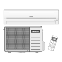
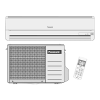
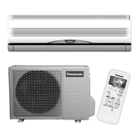
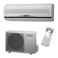
Visual guide showing the placement and connection of indoor and outdoor units.
Details on selecting the best location and fixing the indoor unit installation plate.
Instructions for creating a wall opening for piping and installing a protective sleeve.
Steps for installing piping when it is concealed within walls or structures.
Procedures for connecting the indoor unit, including piping and cables.
Guidance on routing the piping and drain hose, especially for embedded installations.
Detailed steps for connecting the electrical cable to the indoor unit terminals.
Steps to remove the front grille for access to internal components.
Instructions for mounting the outdoor unit securely at the selected location.
Procedures for connecting refrigerant piping to both indoor and outdoor units.
Techniques for cutting and flaring copper pipes according to specifications.
Procedure for removing air and moisture from the refrigeration cycle.
Steps to remove remaining air and moisture from the refrigeration circuit.
Details on connecting the electrical cable to the outdoor unit's control board.
Guidance on insulating refrigerant pipes to prevent condensation and heat loss.
Recommendations for disposing of drain water from the outdoor unit.
Procedure for verifying proper drainage function after installation.
Checks to evaluate the unit's performance after installation, including temperature differences.
Introduction to R410A refrigerant, its properties, and comparison with R22.
Discusses the types of oils compatible with R410A and handling precautions.
Essential safety precautions when handling R410A refrigerant piping.
Lists necessary ordinary and R410A-specific tools for piping work.
Provides specifics on R410A tools like gauges, flaring tools, and torque wrenches.
Compares R410A manifold gauges with conventional types.
Details R410A charging hoses and vacuum pump adaptor requirements.
Information on using a gas leak detector suitable for HFC refrigerants.
Explains the use of electronic scales for accurate refrigerant charging.
Covers R410A refrigerant cylinder types and charging orifice requirements.
Specifies the required types and thickness of copper pipes for R410A systems.
Details the procedure for processing and connecting refrigerant piping materials.
Provides tables for R410A flaring dimensions and torque specifications.
Guidance on storing and managing refrigerant pipe materials.
Specific advice on handling copper pipes to prevent contamination and damage.
General precautions to follow during refrigerant piping work.
Procedure for checking gas leaks using a vacuum pump for new installations.
Steps for removing and transferring refrigerant when using new piping.
Checks and procedures for replacing AC units using existing refrigerant piping.
Discusses compatibility issues between R410A and R22 AC systems.
Procedure for recharging refrigerant during maintenance or repair.
Detailed steps for charging liquid refrigerant using an electronic scale.
Guidance on brazing techniques, emphasizing safety and quality.
Methodology for brazing to prevent oxidation and ensure circuit integrity.
Advice on replacing the drier component during servicing operations.
Step-by-step guide for removing the intake grille from the unit.
Instructions for safely removing the front grille assembly.
Steps to disassemble and remove the electronic control board and related components.
Instructions for detaching and removing the discharge grille.
Detailed steps for disassembling and removing the cross-flow fan assembly.
Procedure for resetting the remote control if the display becomes chaotic.
Guide to diagnosing issues related to the refrigeration cycle, including pressure and temperature.
Explains how to measure and interpret air temperature differences for diagnostics.
Procedure for measuring electric current to diagnose operational issues.
Methods for measuring gas side pressure to identify refrigerant or compressor problems.
Table showing how various conditions affect pressure and electric current.
Methods for diagnosing faults related to the compressor, such as insufficient compression or locking.
Graphs illustrating thermostat behavior in cooling, soft dry, and heating modes.
Graphs showing cooling capacity, current, and pressure vs. outdoor temperature.
Graphs showing heating capacity, current, and pressure vs. outdoor temperature.
Graphs illustrating cooling performance variation with piping length.
Graphs showing heating performance variation with piping length.
Graphs showing cooling capacity, current, and pressure vs. outdoor temperature.
Graphs showing heating capacity, current, and pressure vs. outdoor temperature.
Graphs illustrating cooling performance variation with piping length.
Graphs showing heating performance variation with piping length.
Circuit diagram detailing the internal components and connections of the remote controller.