42
CAUTION
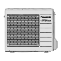
10.3 Outdoor Unit
10.3.1 Install the Outdoor Unit
• After selecting the best location, start installation to Indoor/Outdoor Unit Installation Diagram.
1 Fix the unit on concrete or rigid frame firmly and horizontally by bolt nut (ø10 mm).
2 When installing at roof, please consider strong wind and earthquake. Please fasten the installation stand
firmly with bolt or nails.
Model A B C D
S9*** 474 mm 87 mm 18.5 mm 261 mm
S12*** 570 mm 105 mm 18.5 mm 320 mm
S18***, S24*** 612.5 mm 131 mm 19 mm 383 mm
10.3.2 Connect the Piping
10.3.2.1 Connecting the piping to indoor unit
Please make flare after inserting flare nut (locate at joint portion of tube assembly) onto the copper pipe. (In case of
using long piping)
Connect the piping
• Align the center of piping and sufficiently tighten the flare nut with fingers.
• Further tighten the flare nut with torque wrench in specified torque as stated in the table.
Piping size Torque
1/4" (6.35 mm) [18 Nym (1.8 kgf.m)]
3/8” (9.52 mm) [42 Nym (4.3 kgf.m)]
1/2" (12.7 mm) [55 Nym (5.6 kgf.m)]
5/8” (15.88 mm) [65 Nym (6.6 kgf.m)]
3/4" (19.05 mm) [100 Nym (10.2 kgf.m)]
Do not over tighten, over tightening may cause gas leakage.
10.3.2.2 Connecting the piping to outdoor
Decide piping length and then cut by using pipe cutter. Remove burrs from cut edge. Make flare after inserting the
flare nut (locate at valve) onto the copper pipe. Align center of piping to valve and then tighten with torque wrench to
the specified torque as stated in the table.
10.3.3 Evacuation of the equipment
When installing an air conditioner, be sure to evacuate the air inside the indoor unit and pipes in the following
procedures.
Lo
Hi
OPEN
CLOSE
Gas side
Liquid side
Outdoor unit
Two-way valve
Three-way valve
Indoor unit
 Loading...