– 36 –
MAC9611041C2
CS-MC90KE
Servicing Information
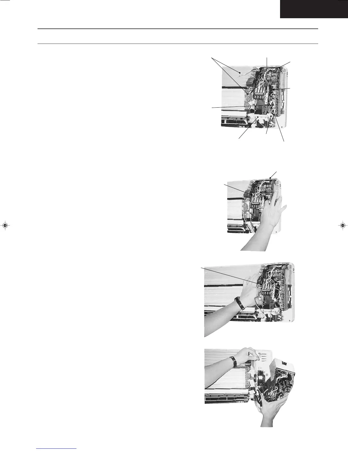
● Inspection points for the Indoor Electronic Control-
ler
1. The Electronic Controller, a signal Receiver and an
Indicator can be seen by removing the Front Grille
and Control Board Cover, as shown in the Fig. 1.
● Indoor Fan Motor removal procedure
1. Remove the connector CN-MTR (GREEN) of Fan
Motor and connector CN-STM (GREEN) of stepping
motor from the electronic controller. Release the
earth wire (YELLOW-GREEN) from the control board
and sensors from its holders. (Refer Fig. 1)
2. Remove the Control Board
The Control Board can be removed by releasing the
top, left and right tabs shown in Fig. 2, 3, 4.
Sensors Earth Wire Connector
Electronic
Connector
(CN-MTR)
Electronic
Controller
Indicator
Stepping Motor Connector
(CN-STM)
Signal Receiver
[A ↔ B] selection switch [SW1]
(Used when there are two units in one room)
Top Taps
Releasing the 2 right
tabs by pressing down
the top tab and pushing
up the bottom tab.
Remove the Control Board
Fig. 2
Fig. 4
Releasing the 2 left
tabs by pressing down
the top tab and pushing
up the bottom tabs
Fig. 3
Fig. 1
Untitled-27 6/25/00, 5:34 PM36