Do you have a question about the Panasonic CU-MC140KE and is the answer not in the manual?
Details operation and settings using the remote control unit.
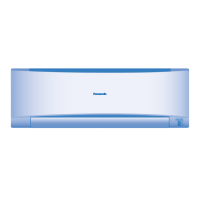
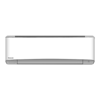
Explains functions, indicators, and controls of the indoor unit itself.
Outlines protective controls and operation details for the outdoor unit.
Provides detailed measurements and diagrams for the CS-MC90KE indoor unit.
Shows dimensions for CU-MC140KE, CU-MC180KE, and CU-3MC200KE outdoor units.
Illustrates the refrigeration cycle for CS-MC90KE / CU-MC140KE models.
Illustrates the refrigeration cycle for CS-MC90KE / CU-MC180KE models.
Illustrates the refrigeration cycle for CS-MC90KE / CU-3MC200KE models.
Electrical system overview for CS-MC90KE / CU-MC140KE units.
Electrical system overview for CS-MC90KE / CU-MC180KE units.
Electrical system overview for CS-MC90KE / CU-3MC200KE units.
Electrical schematic for CS-MC90KE / CU-MC140KE units.
Electrical schematic for CS-MC90KE / CU-MC180KE units.
Electrical schematic for CS-MC90KE / CU-3MC200KE units.
Explains how the unit operates in cooling mode, including controls.
Details the unit's operation in Soft Dry mode, fan speeds, and timings.
Describes the air circulation mode and its stopping conditions.
Explains how the unit automatically determines operation mode and temperature.
Covers auto and manual fan speed adjustments for user comfort.
Details auto and manual airflow direction adjustments for optimal comfort.
Lists all accessories provided with the unit for installation purposes.
Guidelines for choosing optimal installation locations for indoor and outdoor units.
Illustrates the physical setup and connections for indoor and outdoor units.
Description and diagram of the 3-way valve for the liquid side.
Description and diagram of the 3-way valve for the gas side.
Points for inspecting the indoor electronic controller and related parts.
Step-by-step guide for removing the indoor fan motor.
Instructions for removing the cross flow fan assembly.
Details auto/manual operation modes for the solenoid control valve.
Procedure for changing remote control transmission codes for dual units.
Guide to diagnosing issues by measuring temperatures and pressures.
Relates unit conditions, pressure, and electric current to identify faults.
Methods for diagnosing compressor malfunctions based on symptoms.
Graphs showing thermostat behavior for Cooling and Soft Dry modes.
Performance data graphs for cooling capacity, current, and pressure.
Diagram showing the assembly breakdown of the CS-MC90KE indoor unit.
Diagram showing the assembly breakdown of the CU-MC140KE outdoor unit.
Diagram showing the assembly breakdown of the CU-MC180KE outdoor unit.
Diagram showing the assembly breakdown of the CU-3MC200KE outdoor unit.
Part numbers for components of the CWA74813 electronic controller.
Part numbers for components of CWA741123 & CWA741165 controllers.
| Brand | Panasonic |
|---|---|
| Model | CU-MC140KE |
| Category | Air Conditioner |
| Language | English |