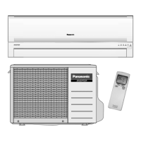
What to do if my Panasonic Air Conditioner is leaking water from the indoor unit?
- JJared BarrettAug 13, 2025
If you notice a water leak from the indoor unit of your Panasonic Air Conditioner, call the dealer immediately.
What to do if my Panasonic Air Conditioner is leaking water from the indoor unit?
If you notice a water leak from the indoor unit of your Panasonic Air Conditioner, call the dealer immediately.
What to do if the circuit breaker switches off frequently when using my Panasonic Air Conditioner?
If the circuit breaker switches off frequently when you are using your Panasonic Air Conditioner, call the dealer immediately.
What to do if my Panasonic CU-V7CKP5 Air Conditioner remote control doesn’t work?
If the remote control or display of your Panasonic Air Conditioner isn't working, check the battery status and verify proper battery insertion, ensuring the (+) and (–) are correctly aligned.
Why does my Panasonic CU-V7CKP5 produce loud noise during operation?
The loud noise you hear during the operation of your Panasonic Air Conditioner is the sound of refrigerant flowing inside the unit.
What to do if I hear abnormal noise during Panasonic CU-V7CKP5 Air Conditioner operation?
If you hear an abnormal noise during the operation of your Panasonic Air Conditioner, call the dealer immediately.
What to do if switches or buttons do not operate properly on my Panasonic CU-V7CKP5?
If the switches or buttons on your Panasonic Air Conditioner do not operate properly, call the dealer immediately.
What to do if the power supply cord and plug become unusually warm on my Panasonic Air Conditioner?
If the power supply cord and plug become unusually warm on your Panasonic Air Conditioner, call the dealer immediately.
Why does my room have a peculiar odour when using Panasonic CU-V7CKP5?
If your room has a peculiar odour when using your Panasonic Air Conditioner, this may be a damp smell emitted by the wall, carpet, furniture or clothing in the room.
Details on remote control operations and settings for various modes.
Electrical resistance values for indoor fan motor windings.
Electrical resistance values for outdoor fan motor windings.
Electrical resistance values for compressor windings.
Details on cooling operation modes, controls, and safety features.
Description of the quiet mode operation and its effects.
Information on the soft dry mode operation and its characteristics.
Explanation of the air circulation mode operation.
Details on the automatic mode operation and temperature determination.
Description of the powerful mode for quick temperature adjustment.
Guidance on setting indoor fan speeds for different modes.
Control methods for vertical airflow direction.
Details on automatic vertical airflow direction adjustment.
Details on manual vertical airflow direction adjustment.
Information regarding the ionizer function and its operation.
Procedure for detecting and resetting ionizer errors.
Case studies illustrating ionizer operation scenarios.
Essential safety guidelines for operating the air conditioner.
Precautions to be followed during the installation process.
Important precautions for safe and proper operation.
Identification of parts for Indoor Unit, Outdoor Unit, and Accessories.
Instructions on how to operate the air conditioner.
Step-by-step guide for inserting batteries into the remote control.
Guidance on adjusting the fan speed for optimal comfort.
Instructions for cleaning the indoor unit and remote control.
Procedure for cleaning the air filters for efficient operation.
Checks to perform before the cooling or heating season.
Information on the auto operation button and its functions.
Explanation of the auto restart feature after power failure.
Tips for energy-efficient temperature settings.
Common phenomena during normal operation.
Troubleshooting guide for abnormal operating conditions.
Conditions requiring immediate professional service.
Crucial safety precautions for installation.
Instructions for installing the indoor unit.
Guidance on selecting the optimal location for the indoor unit.
Instructions for installing the outdoor unit.
Guidance on selecting the optimal location for the outdoor unit.
Procedure for connecting refrigerant piping.
Procedure for evacuating air from the system for specific regions.
Process for purging air from piping and the indoor unit.
General overview of the R410A refrigerant and its characteristics.
Detailed information about R410A refrigerant properties and comparisons.
Safety measures for handling R410A refrigerant piping.
List of necessary tools for refrigerant piping work.
Specific tools required for installation and servicing.
Details on specialized tools for R410A refrigerant.
Tool for adjusting copper tube clearance during flaring.
Description of the R410A compatible flaring tool.
Information on torque wrenches for proper connections.
Details on manifold gauges for pressure readings.
Specifications for charging hoses compatible with R410A.
Electronic scale for accurate refrigerant charging.
Compatibility of R410A tools with R22 models.
Guidelines for performing refrigerant piping work.
Specifications and recommendations for piping materials.
Procedures for preparing and connecting piping materials.
Proper storage and management of piping materials.
Procedures for installation, transfer, and servicing of the unit.
Method for inspecting gas leaks using a vacuum pump.
Procedure for transferring the unit with new refrigerant piping.
Helpful tips for servicing the air conditioner unit.
Steps to remove and service indoor electronic controllers.
Procedure for removing indoor fan motor and cross flow fan.
Procedure for resetting the remote control.
Diagnosing malfunctions related to the refrigeration cycle.
Correlating AC conditions with pressure and electric current readings.
Methods for diagnosing compressor malfunctions.
Characteristics of the thermostat settings for different modes.
Charts detailing sensible capacity under various conditions.
Operating characteristics for CS-V7CKP / CU-V7CKP5 models.
Operating characteristics for CS-V9CKP / CU-V9CKP5 models.
Operating characteristics for CS-V12CKP / CU-V12CKP5 models.
First part of the electronic circuit schematic.
Second part of the electronic circuit schematic.
Third part of the electronic circuit schematic.
| Brand | Panasonic |
|---|---|
| Model | CU-V7CKP5 |
| Category | Air Conditioner |
| Language | English |


 Loading...