The parking brake switch position varies
with the vehicle model.
Side Brake (Parking Brake) Connection Lead (Blue / yellow stripe)
When the parking brake lever is engaged, the unit is grounded by the chassis.
q
Attach a Clip Connector !8 to the end of the parking
brake connection lead.
w The Clip Connector !8 is connected to the power
source side lead of the parking brake lever.
Comes up to this point
Side Brake (Parking Brake) Connection Lead
(Blue / yellow stripe)
Power Source Side Lead
Caution: For safety, be sure to ask your nearest professional installer to do this connection.
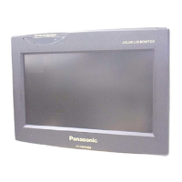
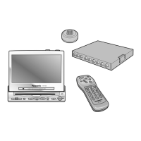
Connection with VCR or Camcorder
Connecting the Parking Brake Connection Lead
Note: Refer to the operating instructions for the connected devices, in addition.
 Loading...