AUDIO OUT
L
R
OPTICAL
VIDEO OUT
S VIDEO OUT
COMPONENT VIDEO OUT
Y
P
P
B
R
RF OUT
RF IN
AV 2 (EXT)
AV 1 (TV)
AC IN
AV OUT
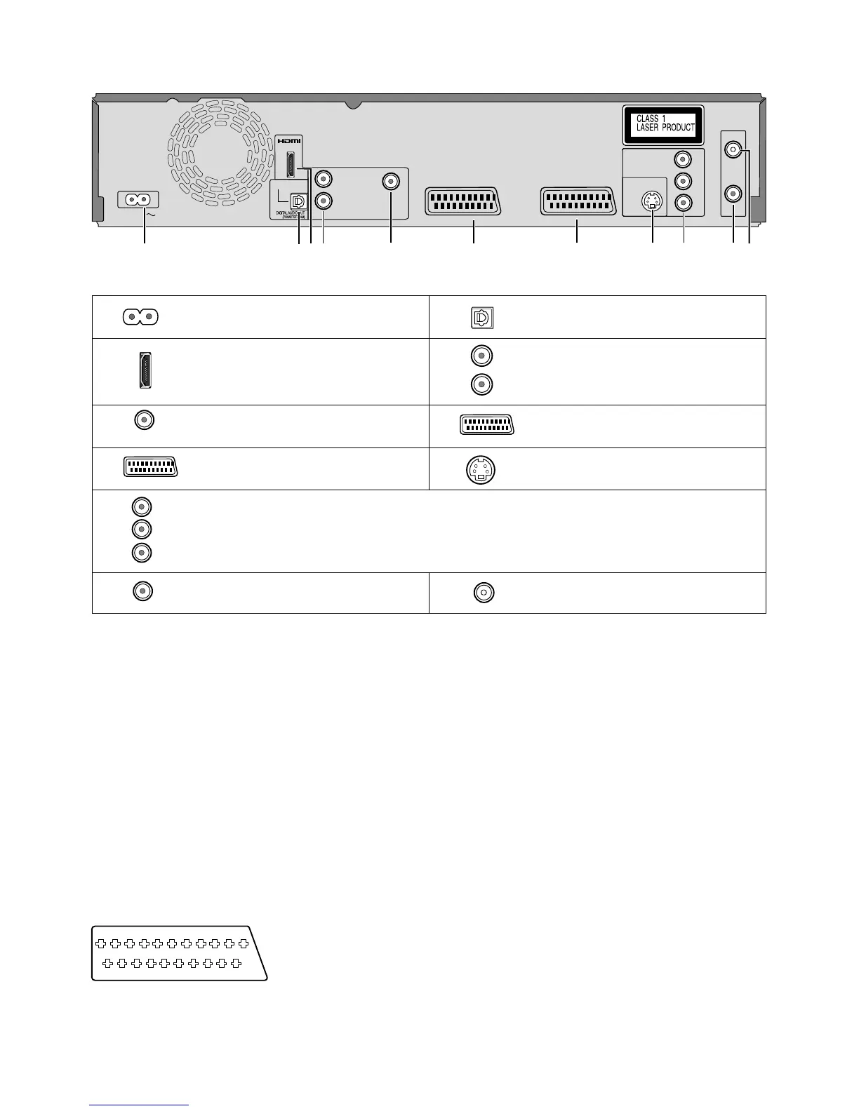
Rear Panel
1
3
4
5
6 7
2
8 9
10
11
9
1
2
HDMI AV OUT
Digital audio output
3
4
5
6
7
8
9
10
11
COMPONENT VIDEO OUT
Y
P
B
P
R
AV1 (TV)
L
R
AV2 (EXT)
VIDEO OUT
Y = Luminance signal (brightness)
P = Chrominance signal (colour difference)
B
P = Chrominance signal (colour difference)
R
AV1 (TV) = 21-pin Scart terminal
TV connection
AV2 (EXT) = 21-pin Scart terminal
External unit connection
OPTICAL
Digital audio output
AC IN~ = Power supply
RF IN
Aerial input
RF OUT
Aerial output
S VIDEO OUT
S VIDEO output terminal
Connection for the AC mains lead.
Audio output, right/left channel
Video output
For a conventional tube television, we recommend using the Scart terminal.
You retain a high-quality RGB video picture with an RGB-compatible television.
!
If you want to use a progressive-capable LCD/plasma television or LCD projector, connect it to COMPONENT VIDEO OUT to get a high quality
progressive video picture.
The outputs of 3, 4, 5, 8 and 9 are dedicated to modules of digital signal processing (DVD).
The video and audio outputs of 6 and 7 are dedicated to modules of digital (DVD) or analogue (VHS) signal processing.
Both groups of outputs are used for analogue and digital sources. But there are limitations, e.g.: During recording or scheduled recording on DVD, the VHS
playback is only possible on outputs of 6 and 7.
AUDIO OUT
21-pin Scart terminal
19
20
21
1
3
5
7
9
11
13
15 17
2
4
6
8
10 12 14 16 18
The 21-pin Scart terminal transmits both input
and output signals for picture and sound.
TVs equipped with the same type of terminal
can be connected here.
This type of terminal is also called Peritel,
Euro Connector and Euro AV.
AV1 Scart terminal (TV) AV2 Scart terminal (EXT)
1 Audio output CH2 (R) 1 Audio output CH2 (R)
2 Audio input CH2 (R) 2 Audio input CH2 (R)
3 Audio output CH1 (L) 3 Audio output CH1 (L)
4 Audio ground 4 Audio ground
5 Blue ground 5 Blue ground
6 Audio input CH1 (L) 6 Audio input CH1 (L)
7 Blue output 7 Blue input
8 Switching voltage 8 Switching voltage
9 Green ground 9 Green ground
10 Q Link control signal 10 Reserved
11 Green output 11 Green input
12 Reserved 12 Reserved
13 Red ground 13 Red ground
14 Blanking ground 14 Blanking ground
15 Red output / chrominance output 15 Red input / chrominance input
16 Blanking output 16 Blanking input
17 Video output ground 17 Video output ground
18 Video input ground 18 Video input ground
19 Video output / luminance output 19 Video output
20 Video input 20 Video input / luminance input
21 Ground 21 Ground
 Loading...