Do you have a question about the Panasonic DMP-BD75GA and is the answer not in the manual?
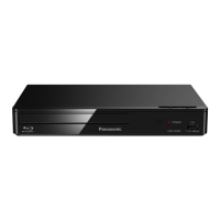
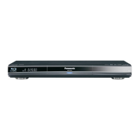
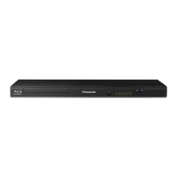
Identifies the product type as a Blu-ray Disc Player.
Specifies the model number DMP-BD75GA.
General safety guidelines and procedures for leakage current checks.
Important caution regarding the replacement of fuses.
Procedure for checking the micro fuse conductivity.
Guidelines for preventing damage from static electricity to sensitive devices.
General information about the service manual's content and usage.
Using combinations of buttons on the remote control for special functions.
How to enter special modes using remote control button combinations.
Procedure and functions for the Disclosure mode.
Procedures and functions for Nondisclosure modes 1 and 2.
Details on power supply requirements and consumption.
Information on operating temperature and humidity ranges.
Specifications related to signal systems and video output.
Specifications for audio output and HDMI interface.
Information on supported media formats and playable discs.
Details on unit dimensions, mass, and solder type.
Detailed explanation of the remote control and unit buttons.
Identification of key components on the unit's front panel and chassis.
Procedure to eject disc when normal eject fails.
Alternative method for manual disc ejection if forcible eject fails.
Provides information on error codes and unit status.
Details on how to set various special modes for servicing.
Summary of service modes and their key operations.
Displays BD drive error codes and timing.
CEC output, date, tests, deletions, initializations, and release functions.
Instructions for disassembling the main unit.
Flowchart outlining the steps for disassembling the unit.
Diagram showing the location of the main PCBs.
Procedures for removing the top case, front panel, and rear panel.
Procedures for removing the power, digital, and power switch PCBs.
Procedures for removing the BD drive and its tray.
Procedures for removing pulley gear, belt, slide cam, drive gear, and loading motor.
Disassembly, assembly, and lubrication of the optical pick-up unit.
Procedure for cleaning the optical pick-up lens.
Flowchart for diagnosing and repairing unit issues.
Procedures for analyzing and distinguishing component failures.
General information on service positions for measurement and adjustment.
Procedures for checking and repairing Power and Digital PCBs.
Steps to be performed after replacing parts.
Checklist for verifying normal operation after repairs.
Diagram showing the overall functional blocks of the unit.
Diagram showing the power supply circuitry.
Diagram showing interconnections between major components.
Detailed schematic of the power supply section.
Schematic diagram of the LED control section.
Schematic diagram of the power switch section.
Layout diagrams of the Power and Power SW PCBs.
Reference voltages and waveforms for troubleshooting.
List of abbreviations used throughout the manual.
Exploded diagrams of casing parts and the mechanism section.
Exploded diagrams of packing materials and accessories.
List of mechanical replacement parts with part numbers.
| Brand | Panasonic |
|---|---|
| Model | DMP-BD75GA |
| Category | Blu-ray Player |
| Language | English |