Do you have a question about the Panasonic DMR-E53EG, DMR-E55EB, DMR-E55EG, DMR-E55EBL, DMR-E55EP and is the answer not in the manual?
Observes original lead dress, protective devices, and leakage current checks for customer safety.
Measures resistance between AC plug and exposed parts to ensure safety.
Measures AC voltage across a resistor connected to exposed parts and earth ground for safety.
Techniques to reduce component damage from static electricity during handling.
Critical parts marked for safety; do not modify original design.
Caution against disassembling, adjusting, or looking at the laser pickup unit.
Information and precautions for working with lead-free solder.
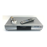
Explains the function of each button on the remote control.
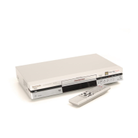
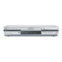
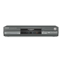
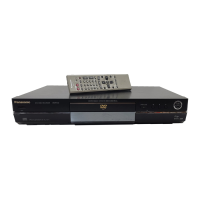
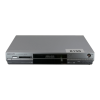
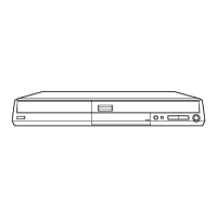
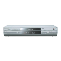
Identifies key components and terminals on the main unit.
Explains the meaning of various indicators on the unit's display.
Procedures for ejecting a disc when the normal button fails.
Steps for physically removing a disc when forcible eject fails.
Steps to enter the service mode and confirm "RAM-Drive Last Error".
Explains how error numbers, timestamps, and drive errors are displayed.
Lists error codes for disc types and identifies disc manufacturers.
Explains disc distinction and state codes related to errors.
Details error codes related to different disc types.
Details error codes related to the state of the disc cartridge.
Provides information for errors to service personnel via "Self-Diagnosis Display".
Details various special modes and their key operations.
How to enter service mode and release items.
Displays ROM versions, region codes, and error codes.
Modes for testing picture output, audio mute, and patterns.
Modes for RAM Drive error, FL/LEDs, signal output, and front inspection.
Modes for error history, I/O settings, P50 output, and tray cycle test.
Procedures for initializing service settings and exiting service mode.
Procedure for disassembling casing and internal parts for inspection.
Diagrams showing the positions of various PCBs within the unit.
Steps for removing the top cover of the unit.
Steps for removing the digital printed circuit board.
Steps for removing the front panel.
Steps for removing the front (R) printed circuit board.
Steps for removing the rear panel.
Steps for removing the DVD-RAM drive unit.
Steps for removing the main printed circuit board.
Steps for removing the power printed circuit board.
Steps for removing the Scart printed circuit board.
Steps for removing the VIF and Nicam Decoder PCBs.
Lists part numbers for extension cables and fixtures for servicing.
Step-by-step guide for accessing and working on the power PCB.
Step-by-step guide for accessing and working on the main PCB.
Step-by-step guide for accessing and working on the digital PCB.
Step-by-step guide for accessing and working on the DVD-RAM drive.
Steps for confirming operation after replacing the RAM drive.
Steps for normal operation after replacing the Timer Microprocessor.
Recommended checks after making repairs for normal operation.
Table of voltage measurements for various points on the Power PCB.
Table of voltage measurements for various points on the Main PCB.
Table of voltage measurements for the Nicam Decoder PCB.
Table of voltage measurements for the Scart PCB.
Table of voltage measurements for the Front (R) PCB.
Table of voltage measurements for the P9001 connector.
Visual representations of signal waveforms measured with PAL colour bar.
Lists initialisms and acronyms used in the manual.
Continues the list of initialisms and acronyms used in the manual.
Exploded view diagram of external and internal casing parts.
Exploded view diagram of front chassis and related parts.
Exploded view of unit packaging and included accessories.
Important safety notice and notes on part identification.
Lists part numbers for casing, PCBs, and accessories.
Lists part numbers for various electronic components (capacitors, diodes, ICs).
Lists part numbers for resistors and transistors.
Lists remaining part numbers for various electronic components.