Do you have a question about the Panasonic DMR-ES15EB and is the answer not in the manual?
Introduction to self-diagnosis functions and special modes for service personnel.
Flow chart detailing the procedure for disassembling the casing and internal parts for inspection.
Information related to service positions for checking and repairing components.
List of necessary actions after replacing specific parts, like resetting EEPROM or obtaining new registration codes.
Overall interconnection schematic showing how different parts of the unit connect.
Detailed schematic of the power supply section of the unit.
Detailed schematics of the main PCB, covering main nets and A/V I/O sections.
Detailed schematics for the Nicam decoder and timer sections of the main PCB.
Detailed schematic of the tuner pack circuitry.
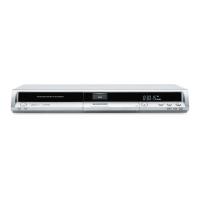
| Type | DVD Recorder |
|---|---|
| Recording Format | DVD-RAM, DVD-R, DVD-RW |
| Video Format | PAL |
| Video Recording Format | MPEG-2 |
| Audio Format | Dolby Digital |
| Digital Tuner | No |
| Analogue Tuner | Yes |
| Video Recording Modes | XP, SP, LP, EP |
| Progressive Scan | Yes |
| Playback Media | DVD-R, DVD-RW, CD, CD-R, CD-RW |
| Tuner Type | Analog |
| Connectivity Front | S-Video input |
| Connectivity Rear | RF input, RF output |
| Inputs | Composite video, S-Video |
| Outputs | Composite video, S-Video, SCART |
| Dimensions | 430 x 49 x 286 mm |
| Video D/A Converter | 10 bit |
| Audio D/A Converter | 24-bit |