Do you have a question about the Panasonic DMR-ES10P and is the answer not in the manual?
General guidelines for servicing and safety checks.
Procedures for cold and hot leakage current testing.
Warning and specification for fuse replacement.
Critical components marked with A must use manufacturer-specified parts.
Warnings about laser radiation exposure and handling.
Methods for manually ejecting a disc.
Steps for physical removal if forcible eject fails.
Steps to access the service mode for diagnostics.
Explains error codes and diagnostic information.
Accessing error codes and firmware versions.
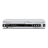
Overall procedure for disassembling the unit.
Diagram showing the placement of PCBs.
Procedure for checking and repairing the power PCB.
Procedure for checking and repairing the digital PCB.
Procedure for checking and repairing the main PCB.
Procedure for checking and repairing the DVD-RAM drive.
Steps for units not operating after component replacement.
Standards for judging picture quality after repairs.
Standards for judging sound quality after repairs.
Block diagram of the power supply system.
Detailed schematic of the main power supply circuit.
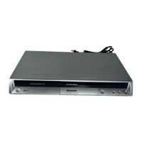
| Type | DVD Recorder |
|---|---|
| Video Format | MPEG-2 |
| Video System | NTSC |
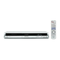
| Progressive Scan | Yes |
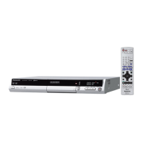
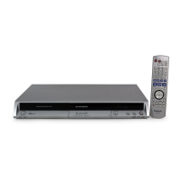
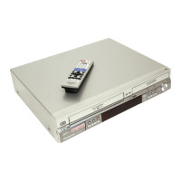
| Remote Control | Yes |
| Hard Drive | No |
| VHS Playback | No |
| VHS Recording | No |
| Time Shift Function | No |
| Recordable Media | DVD-R, DVD-RW, DVD-RAM |
| Recording Format | DVD-Video |
| Audio Format | Dolby Digital |
| Tuner | Analog Tuner |
| Inputs | Composite video, S-Video |
| Outputs | Composite video, S-Video |
| Power Consumption (Standby) | 1 W |
| Dimensions (W x H x D) | 430 x 59 mm |