Do you have a question about the Panasonic DMR-ES35VP and is the answer not in the manual?
Procedures for checking cold and hot leakage currents.
Measures to prevent damage from static electricity to sensitive electronic components.
Overview of DVD service modes, including self-diagnosis and special settings.
Details on DVD self-diagnosis functions and error code interpretation.
Explanation of VHS self-diagnosis error codes and their meanings.
Procedures for activating and using special modes for VHS servicing.
Details on VHS service modes and data display.
Details on VHS error numbers and their associated supplementary data.
Schematic showing how different PCBs and sections are interconnected.
| Brand | Panasonic |
|---|---|
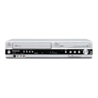
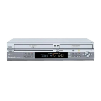
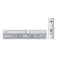
| Model | DMR-ES35VP |
| Category | DVD Recorder |
| Language | English |