Do you have a question about the Panasonic DMR-ES30VEG and is the answer not in the manual?
General safety guidelines for servicing, including handling sharp edges and protective devices.
Procedure for checking leakage current when the unit is cold and unplugged.
Procedure for checking leakage current when the unit is powered on.
General safety advice regarding handling of electrostatic sensitive devices and precautions.
Information and precautions regarding the use of lead-free solder for repairs.
Procedures for grounding equipment and personnel to prevent ESD damage.
Specific handling guidelines for the optical pick-up unit to prevent ESD damage.
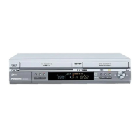
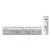
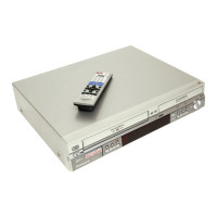
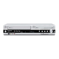
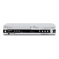
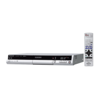
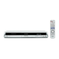
Overview and explanation of front panel buttons and remote control functions for VCR and DVD.
Explanation of the Quick Start recording function for DVD-RAM preparation.
Procedure for ejecting a DVD disc when the unit's power is off or on.
Steps to take if the forcible disc eject procedure fails, involving disassembly.
Method for removing a VHS cassette tape using service mode functions.
Procedure for manual removal of a VHS cassette tape after partial disassembly.
Detailed steps for manually removing a VHS cassette after mechanism disassembly.
Information on error codes and their meanings displayed by the self-diagnosis function.
Instructions for entering and setting various special modes for servicing.
Details on accessing and utilizing specific service modes for diagnosis and adjustment.
Overview of special modes for VHS section servicing and their front panel key operations.
Explanation of VHS service modes, including mechanism operation and motor control.
Details on the VHS self-diagnosis function, error code history, and clearing procedures.
Procedural chart outlining the steps for disassembling the unit for internal inspection.
Diagram showing the locations of various printed circuit boards (PCBs) within the unit.
Important note regarding potential issues when inserting a cassette tape during disassembly.
Instructions for removing and reattaching the top case of the unit.
Detailed steps for removing and reattaching the front panel assembly.
Procedure for removing the front jack and FL drive printed circuit boards.
Instructions for removing and reattaching the rear panel and fan motor assembly.
Procedure for disconnecting and removing the VCR mechanism unit.
Steps for disconnecting and removing the main printed circuit board.
Procedure for removing specific decoder and NICAM PCBs.
Steps for removing the DVD-RAM drive unit from the chassis.
Procedure for removing and handling the digital printed circuit board, including cautions.
Instructions for removing the power and digital interface printed circuit board.
Detailed steps for checking and repairing the power and digital interface PCB.
Procedure for checking and repairing the main PCB, including disassembly steps.
Instructions for checking and repairing the DVD-RAM drive unit.
Precautions and checks after replacing the RAM drive unit.
Steps for resetting the timer microprocessor after replacement.
Note on adjusting PG shifter after replacing the EEPROM.
Procedures for PG Shifter and X-Value/Linearity adjustments after component replacement.
Detailed steps for adjusting X-Value and Linearity for VHS playback.
Procedure to reset the VHS microprocessor IC6001 if the unit does not operate normally.
Displays standard waveforms measured with PAL color bar signal for various test points.
List of abbreviations used in the manual related to DVD functions and components.
List of abbreviations used in the manual related to VHS functions and components.
Block diagram illustrating the power supply circuit and its components.
Block diagram showing the system control, servo, and timer functions.
Block diagram illustrating the audio signal processing path and components.
Block diagram detailing the video signal processing path and components.
Block diagram for the digital interface PCB, showing signal flow and connections.
Schematic diagram of the power supply circuit, showing component layout and connections.
Schematic diagram illustrating the DVD output circuitry and signal paths.
Schematic diagram showing the various interface connections and circuitry.
Schematic diagram for input/output and tuner sections, detailing signal flow.
Schematic diagram for the system control, servo, and timer main board.
Schematic diagram detailing the VHS audio processing circuitry.
Schematic diagram illustrating the video processing circuits for recording and playback.
Schematic diagram of the NICAM decoder circuit, including component connections.
Schematic diagram for the front panel jacks, showing connections to PCBs.
Schematic diagram of the FL (Fluorescent Display) drive circuit.
Component layout diagram for the power and digital interface PCB.
Solder side layout diagram for the power and digital interface PCB.
Component layout diagram for the main PCB.
Solder side layout diagram for the main PCB.
Component layout diagrams for the NICAM decoder PCB (VEP07A51A and VEP07A51B).
Component layout diagrams for the NICAM decoder PCB (VEP07A51E and VEP07A51F).
Component and solder side layout diagrams for the front jack PCB.
Component and solder side layout diagrams for the FL drive PCB.
Exploded view illustrating the mechanism and casing components.
Exploded view showing the parts that make up the front panel assembly.
Exploded view detailing the individual parts of the VHS mechanism.
Diagram showing the packing configuration and included accessories.
List of replacement parts for the VHS mechanism.
List of replacement parts for the main mechanism and casing.
List of replacement PCBs included within the main PCB assembly.
List of replacement parts for packing materials and accessories.
List of electrical components available as replacement parts.
List of specific tools and fixtures required for service and repair.
| Brand | Panasonic |
|---|---|
| Model | DMR-ES30VEG |
| Category | DVD Recorder |
| Language | English |