16 SERVICE POSITIONS
16.1. CHECKING AND REPAIRING OF POWER & DIGITAL I/F P.C.B.
1. Top Case
·
Remove 4 Screws (A) on side and 3 Screws (B) on rear side.
·
Remove Top Case.
2. Front Panel
·
Remove on Screw (A) on center.
·
Unlock 2 Locking Tabs (A), (D) on Front Panel side and 2 Locking Tabs (B), (C) on Front Panel topside.
·
Unlock 3 Locking Tabs (E) on Front Panel bottom side and remove Front Panel.
3. Rear Panel with Fan Motor
·
Remove 5 Screws (A), (B) and (C) on Rear Panel.
·
Unlock 2 Locking Tabs to remove Rear Panel with Fan Motor.
4. VTR Mechanism Unit
·
Disconnect 3 Connectors.
·
Remove 3 black Screws (A) and 3 Screws (B), (C), (D).
·
Lift up VTR Mechanism Unit to remove it.
5. Main P.C.B.
·
Disconnect 5 Connectors from Power & Digital I/F P.C.B.
·
Remove 2 Screws (A) and remove Main P.C.B.
·
Attach VTR Mechanism Unit on to Main P.C.B.
·
Tighten Screw (C) with Earth Wire and tighten Screw (D) beside Screw (C).
·
Insert on Connector and 2 FFCs.
·
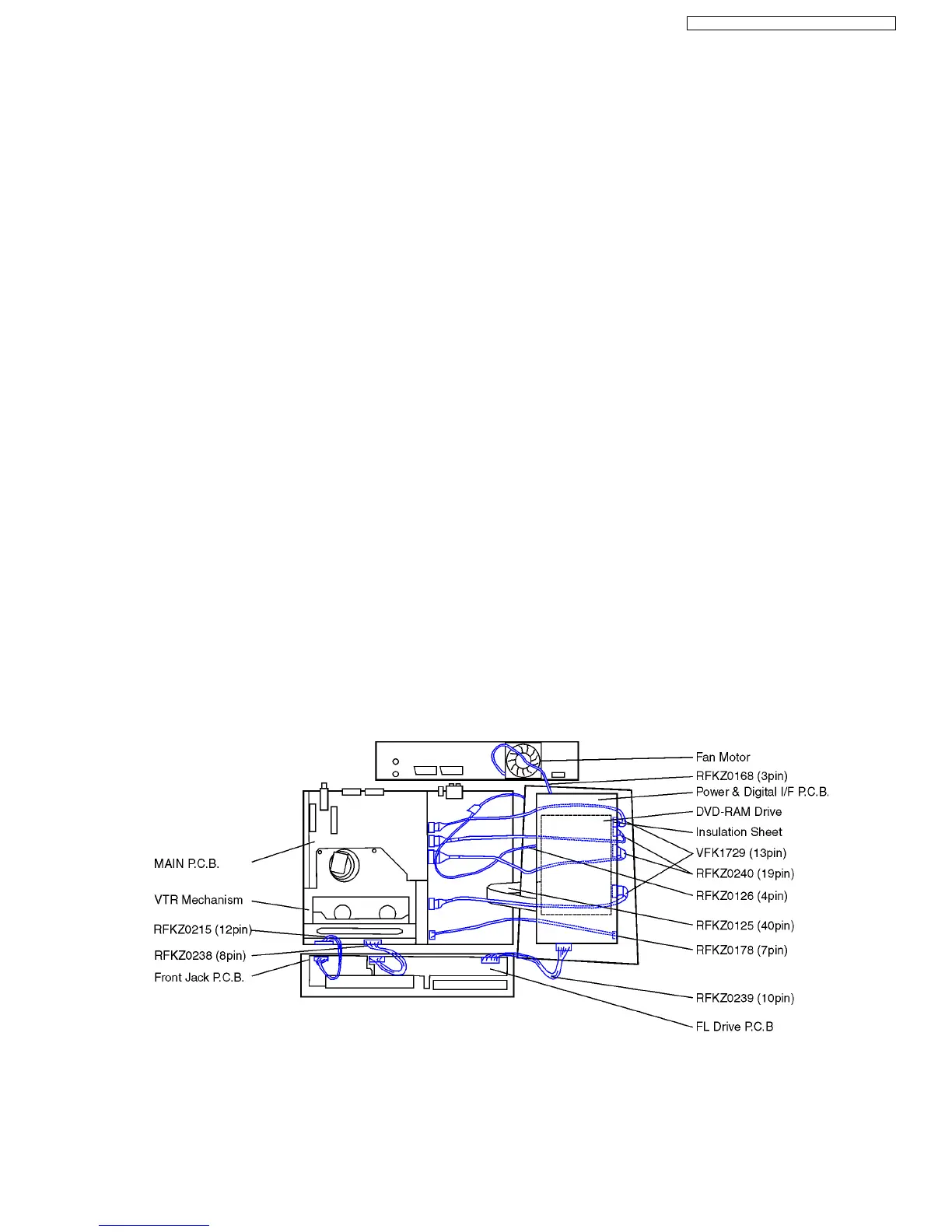
Hold Main P.C.B. with VTR Mechanism, put it upside-down and connect Extension Cables:
−
− −
− between Main P.C.B. and Power Digital I/F: P.C.B. RFKZ0178 (1x), RFKZ0240 (2x), VKF1729 (2x)
−
− −
− between Main P.C.B. and Front Jack P.C.B.: RFKZ0215
−
− −
− between Main P.C.B. and FL Drive P.C.B.: RFKZ0238
−
− −
− between Power & Digital I/F P.C.B. and FL Drive P.C.B.: RFKZ0239
−
− −
− between Power & Digital I/F P.C.B. and Fan Motor: RFKZ0168
39
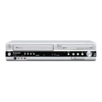
DMR-ES30VEG / DMR-ES30VEC / DMR-ES30VEB
 Loading...