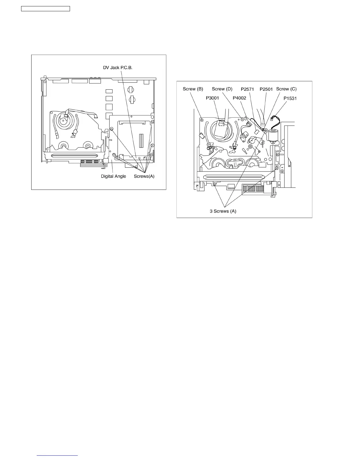
9.8. DV Jack P.C.B.
1. Remove 7 Screws (A).
2. Remove DV Jack P.C.B. with Digital Angle.
9.9. VTR Mechanism Unit
1. Disconnect 3 Connectors (P1531, P2501 and P4002).
2. Remove 3 Black Screws (A), Screw (B) , Screw (C) and
Screw (D).
3. Lift up VTR Mechanism Unit perpendicularly so to
disconnect Connectors (P2571 and P3001).
Note:
Pay attention to stiff connections of P2571 and P3001,
when removing VTR Mechanism Unit.
9.9.1. Caution for attaching VTR
Mechanism Unit
1. Attach VTR Mechanism Unit so that Boss of Position SW is
put into long hole of Main Cam Gear, refer to Fig. (B).
36
DMR-ES35VP / DMR-ES35VPC
 Loading...