Do you have a question about the Panasonic DMR-ES40VP and is the answer not in the manual?
Safety precautions for handling and working with the laser diode.
Setting and performing self-diagnosis and special modes for DVD functions.
Setting and performing self-diagnosis and special modes for VHS functions.
Setting and entering VHS service modes.
Description of service positions for measurements and adjustments.
Procedure for checking and repairing the main PCB.
Procedure for checking and repairing the DVD-RAM drive.
Troubleshooting when unit fails after replacing Timer Microprocessor or Main PCB.
Adjustment procedures for VHS after replacing specific components.
Procedure for adjusting X-Value and Linearity for VHS.
Inspection criteria for checking normal operation after DVD repairs.
Voltage and waveform chart for the main PCB.
Voltage and waveform chart for the power and digital I/F PCB.
Block diagram illustrating the power supply circuit.
| Recordable Media | DVD-RAM, DVD-R, DVD-RW |
|---|---|
| Tuner | NTSC |
| Progressive Scan | Yes |
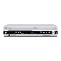
| VHS Playback | Yes |
| VHS Recording | Yes |
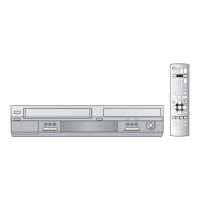
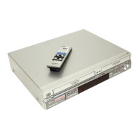
| Remote Control | Yes |
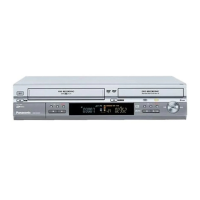
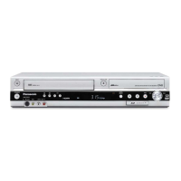
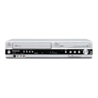
| Type | DVD Recorder |
| Recording Format | DVD-R, DVD-RW |
| Playback Formats | DVD-Video, DVD-RAM, DVD-R, DVD-RW, CD, CD-R, CD-RW, MP3, JPEG |
| Audio Format | Dolby Digital |
| Video D/A Converter | 10-bit |
| Audio D/A Converter | 24-bit |
| Inputs | 1 x S-Video |
| Outputs | 1 x S-Video |