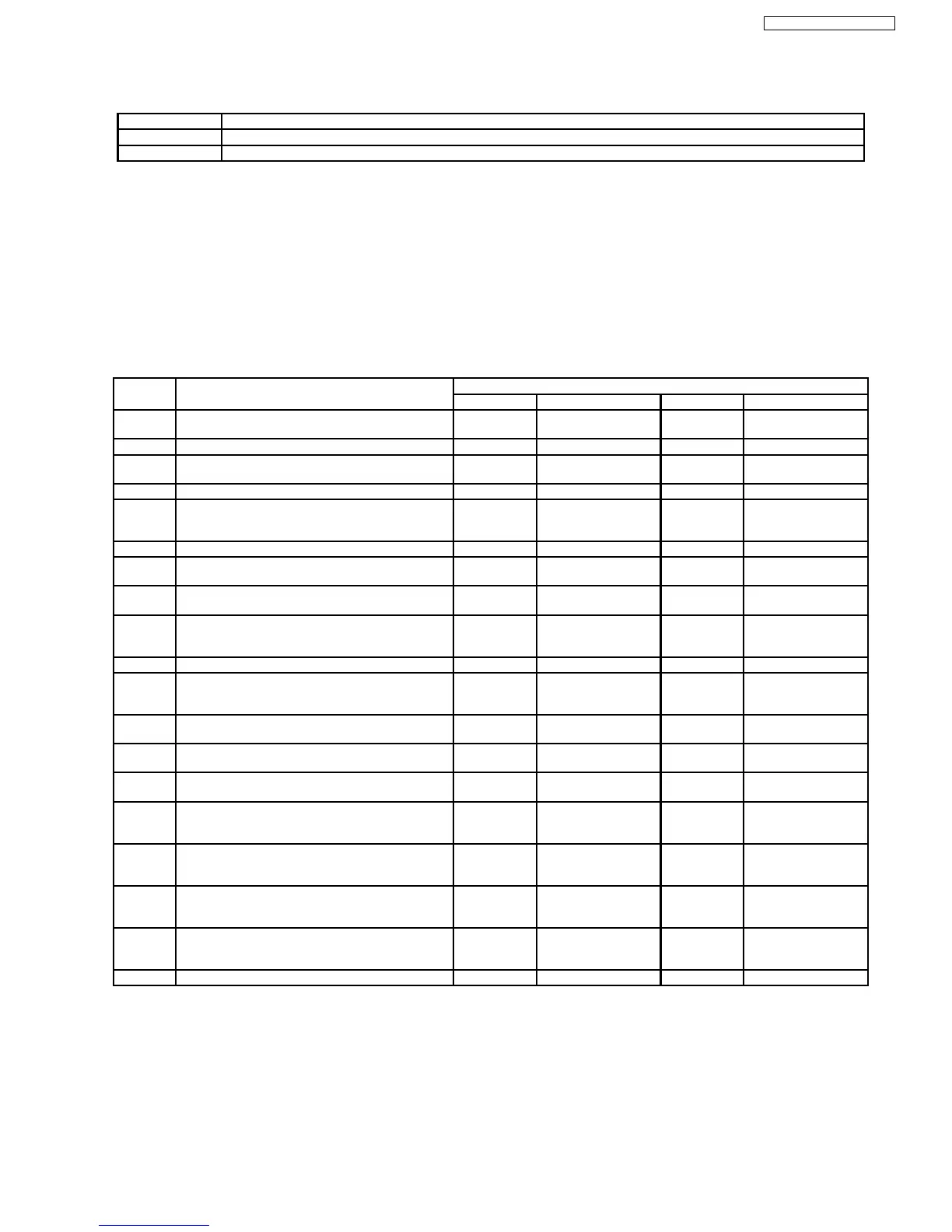
<Supplementary Data 4> (LM Information)
Result of request of driving Loading Motor.
Display Description
1
There was no change of mechanism position. (Loading Motor was OFF)
2
There was some change of mechanism position. (Loading Motor was ON)
7.2.5. (VHS) Description of Self Diagnosis Memory
In this Self-Diagnosis Function, in case error has occurred continuously, maximum of the newest 3 error data are
memorized.
And in order to analyze cause of error, the error number and the supplementary data of mode, mechanism position and
so on are memorized.
7.2.5.1. (VHS) Error Number and Supplementary Data
The Supplementary Data as shown below are memorized to each error number.
Error No. Reason Supplementary Data
Data 1 Data 2 Data 3 Data 4
01 The cylinder could not be started.
(Error of the cylinder or the cylinder driver.)
VHS mode - - -
02 The CAP FG could not be detected. VHS mode - Process No. Number of FG
03 Mechanism lock during without the unloading and the
cassette-up.
VHS mode Standby position Process No. LM information
04 Mechanism lock during unloading VHS mode - Process No. LM information
05 S-reel pulse cannot be detected when a cassette
tape is inserted.
(Error of the S-reel system or the Capstan system.)
VHS mode Tape position Process No. LM information
06 Mechanism lock during the Cassette-up. VHS mode Standby position Process No. LM information
07 The recording circuit can not be operated in REC
mode.
VHS mode - Process No. -
08 The recording circuit is operated in except for REC
mode.
VHS mode - Process No. -
09 Serial communication Error between VHS
Microprocessor (IC6001) and Timer Microprocessor
(IC7501).
- - - -
11 Cylinder clogs during the PLAY mode. VHS mode - Process No. -
15 S-reel pulse cannot be detected when a cassette
tape is inserted.
(Error of the S-reel system or the Capstan system.)
VHS mode Value of S-Reel Pulse
counted
Process No. -
16 Detection of the Cylinder lock during the constant
rotation
VHS mode Tape position Process No. -
17 Detection of S-reel lock during the constant tape
running
VHS mode Tape position Process No. Number of FG
18 Detection of T-reel lock during the constant tape
running
VHS mode Tape position Process No. Number of FG
20 NG1 in the PG Shifter Automatic Adjustment
(The cylinder rotation is unstable during the
automatic adjustment.)
VHS mode - Process No. -
21 NG2 in the PG Shifter Automatic Adjustment
(The vertical sync signal is lacked while over 5
seconds on the alignment tape.)
VHS mode - Process No. -
22 NG3 in the PG Shifter Automatic Adjustment
(The installing position of Heads to the cylinder is our
of specification.)
VHS mode - Process No. -
23 NG4 in the PG Shifter Automatic Adjustment
(The servo is not locked to the cylinder for more than
10 sec.)
VHS mode - Process No. -
80 An exceptional ejection depends on a Error VHS mode Refer to *Note 3 Process No. -
Note 1: Details of "VHS mode" of the Supplementary Data 1 (These values are hexadecimal indication)
0: STOP, 1: EJECT, 2: REW, 3: FF, 4:REV, 5: CUE, 6: SLOW, 7: POWEROFF, 8: PLAY, 9: STIL,
A: REC, B: REC PAUSE, C: ADUB, D: ADUB PAUSE, E: INSERT, F: INSERT PAUSE
Note 2: Explanation of "Tape position" of the Supplementary Data
The Tape position Data is the area data of S-reel that is used for judgment of reducing speed in the Main microprocessor
IC6001, and as the tape position is moved from the starting edge to the finishing edge, the value becomes smaller.
The Tape Data does not become "0" even if the tape reaches the finishing edge as the hub remains, and the tape position
values are different between the large hub and the small hub as the each diameters are different from each other.
27
DMR-ES35VP / DMR-ES35VPC
 Loading...