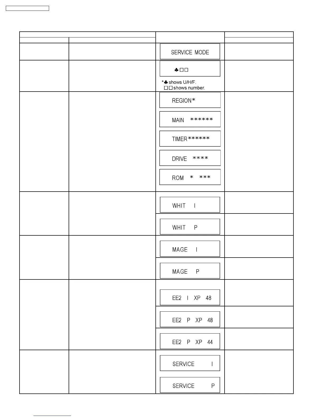
9.3. Service Modes
Service mode setting: While the power is off, press REC, CH UP and OPEN / CLOSE simultaneously for five seconds.
Item FL display Key operation
Mode name Description (Remote controller key)
Release Items Item of Service Mode executing is cancelled. Press [0] [0] or [Return] in service
mode.
Error Code Display Last Error Code of U/H/F held by Timer is
displayed on FL.
*Details are described in “9.1. Self-
Diagnosis Functions”.
Press [0] [1] in service mode
ROM Version Display Region code, MAIN firm version, TIMER firm
version and DRIVE firmware versions are
displayed on FL for five seconds per each
version in order, but ROM version will be left
displayed.
‘’*’’ are version displays.
Press [0] [2] in service mode
White Picture Output White picture is output as component Output
from AV Decoder.
*White picture
(Saturation rate : 100%)
*It is enable to switch Interlace/Progressive by
“I/P switch: [1] [4]”
*Initial mode is “Interlace”. Press [1] [1] in service mode.
Switch Interlace/Progressive Press [1] [4] in White Picture Output
mode.
*I/P are switched alternately.
Magenta Picture Output Magenta picture is output with Component
Output from AV Decoder.
*Magenta picture
(Saturation rate: 100%)
*It is enable to switch Interlace/Progressive by
“I/P switch: [1] [4]”
*Initial mode is “Interlace”. Press [1] [2] in service mode.
Switch Interlace/Progressive Press [1] [4] in Magenta Picture
Output mode.
*I/P are switched alternately.
RTSC Return in XP
(A & V)
L1 input signal is encoded (XP), decoded
(XP) and output decoded signal to external
without DISC recording and DISC playback.
Initial mode: EE2/ Interlace/ XP/
Audio 48kHz
Press [1] [3] in service mode.
Switch Interlace/Progressive Press [1] [4] in RTSC Return XP
mode.
*I/P are switched alternately.
Audio 44.1 kHz/ 48 kHz Switch Press [2] [4] in RTSC Return XP
mode.
*48 kHz / 44.1 kHz are switched
alternately.
I/P Switch Switch Interlace and Progressive in EE mode.
*Initial setting is “Interlace”.
*This command is effective during executing
“White Picture Output”, “Magenta Picture
Output” and “RTSC Return in XP (A & V)”
modes.
Initial mode is Interlace
Switch Interlace/Progressive
Press [1] [4] in I/P Switch mode.
*I/P are switched alternately.
16
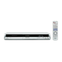
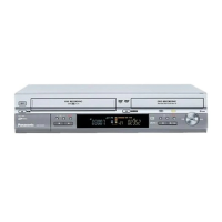
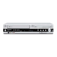
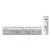
DMR-ES10P / DMR-ES10PC
 Loading...