5 - 22
5
Mini VRF SYSTEM
Trouble Diagnosis
3. Mini VRF System Alarm Codes
4. Mini VRF System Alarm Codes
Mini VRF SYSTEM
Trouble Diagnosis
2
Remove the short
2-1
Are the CHK pin, TEST pin and/or DISP pin on the indoor unit
control PC board short-circuited?
Is the indoor unit powered off?1-1
1-2
3-4
Is the remote control group's wiring opened?2-1
Is the wiring of the remote control group wired according to the
wiring diagram?
2-3
Run the auto address setting again.2-4
Run the auto address setting again after correcting the wiring of the remote control group.2-5
Power on
1-2
Correct the wiring
2-2
2-4
2-5
Yes
Yes
Yes
Yes
No
No
No
2-3
3-1
Yes
No
No
Check the group settings (Item Code 14) from the remote control's
detailed settings mode. Is the main remote controller (1) set to more
than one remote controller or to separate (0)?
2-2
Substitute
Sub
Remote
Controller
3
1 Indoor Unit
E18 Faulty Communication in Group Control Wiring
Error Detection Method
Error Diagnosis
When the main remote controller cannot communicate with a sub remote controller in the remote control group.
It is judged an error if a sub remote controller in a remote control group fails to communicate with the main remote controller
for a period of three minutes.
An indoor unit within the control group does not have its power on.
The CHK pin and/or TEXT pin on the indoor unit in the control group are shorted.
Remote control group wiring is opened.
More than one indoor unit in the control group is set to Main.
An indoor unit in the control group is set to Separate.
•
•
•
•
•
The DISP pin of an indoor unit sub remote controller in the control group is shorted.
•
1.
2.
Replace all optional control PC board and/or wireless remote control parts including wiring.
Replace the indoor unit control PC board.
3-3
Is the wireless remote controller and/or optional control PC board
connected to on the indoor unit’s control PC board?
3-1
Disconnect the connector mentioned above on the control PC board
of the indoor unit control PC board, and see whether the E18 goes off
after several minutes. (When doing so, if two remote controllers are
being used and the wireless remote controller is the main remote
controller, set the other remote controller as the main.)
3-2
Yes
3-2
3-4No
3-3
3-4
Yes
No
Indoor
unit
control
PCB
CHK Pin
CHK Pin
RC
RC
DISP Pin
DISP Pin
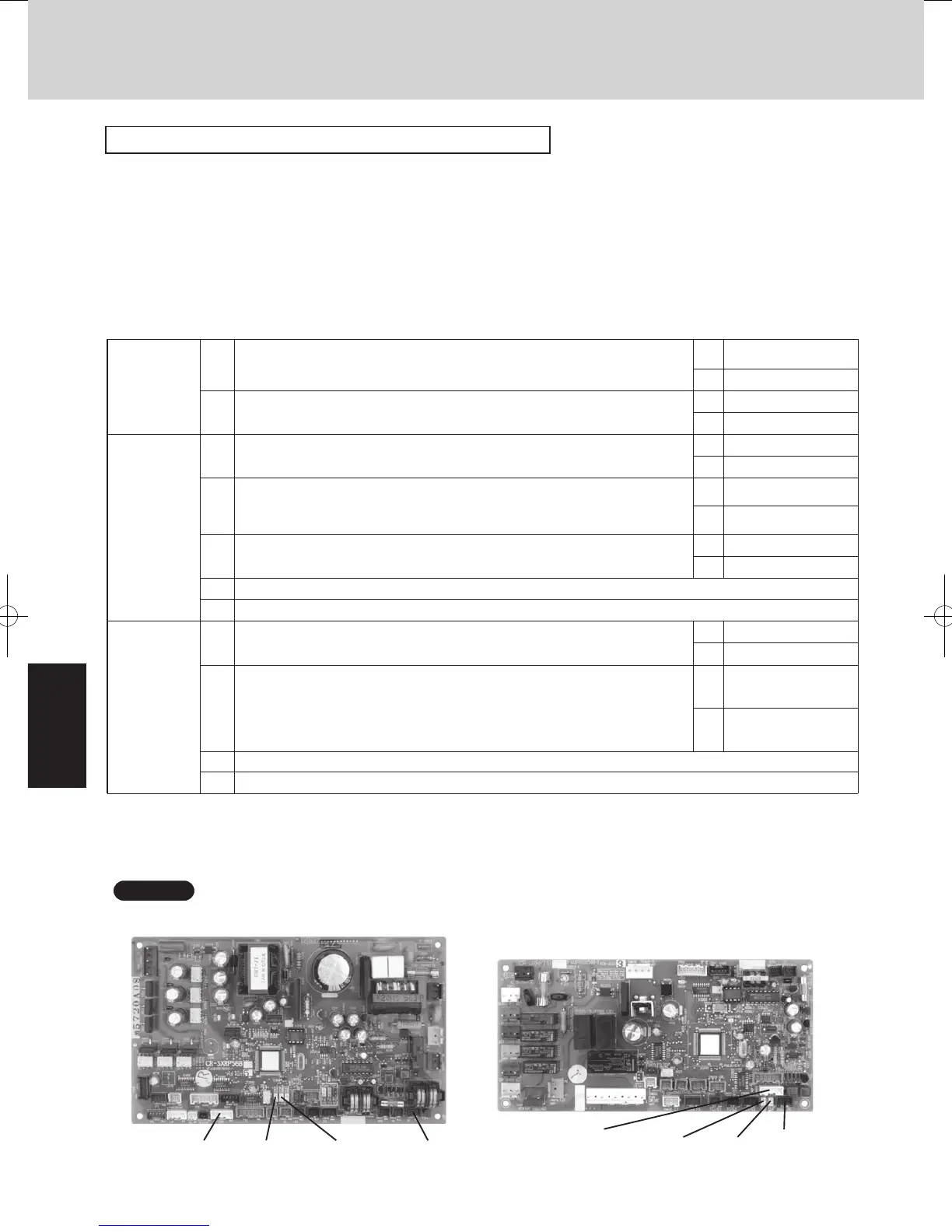
OPTION
AC Motor Model Indoor Unit Control PC Board
OPTION
DC Motor Model Indoor Unit Control PC Board
The ‘/’ in the table indicates the DC motor’s indoor unit board/AC motor’s indoor unit board.
•
There is no TEST pin on the AC motor model’s indoor unit board.
•
For information on the remote control’s detailed settings, refer to the Reference Materials.
•
For information on the procedures for replacing the Indoor unit control PCB, refer to the manual that is packaged with the
indoor unit service board.
•
Regarding the PCB photos for individual indoor units, refer to the Section “PCB AND FUNCTIONS” in the TECHNICAL DATA .
NOTE
SM830195-04_Mini VRF SYS.indb 22 15/02/16 18:01:30
 Loading...