2 - 14
2
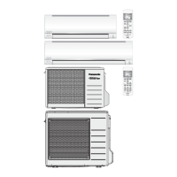
Mini VRF SYSTEM
Outdoor Unit Repair Procedures
(1)
(2)
(a) Compressor
(b) Unit
(1)
(2)
(3)
(4)
(5)
(6)
7-1. Compressor Trouble Diagnosis and Check Methods
Generally, compressor failures can be classified into the following categories.
Mechanical trouble
Electrical trouble
(A) Locking (intrusion of foreign objects, galling, etc.)
(B) Pressure rise failure (damaged valve, seal, bearing, or other component)
(C) Noise (damaged stator, rotor, valve, or other component)
(A) Coil burning
(B) Open circuit
(C) Insulation failure
(D) Short circuit
Failure diagnosis is based on the following remote controller displays: [H01], [H02], [H03] (Compressor : right side
when viewed from front). A judgment is made based on factors that include the following: coil resistance (varies
depending on the compressor), insulation resistance, current, leakage breaker operation, oil and refrigerant f
odor, pressure, and noise.
Reference: Insulation resistance (Use a DC 500 V insulation resistance meter and measure the insulation
resistance between the electrified and non-electrified parts.)
Reference: Symptoms of motor burning
1. Ground fault results in breaker operation.
2. Short circuit results in different coil resistance at different phases.
3. Open circuit
7-2. Compressor Replacement
Follow the instructions in “7-4. Replacing the Compressor” and replace compressor in the failed unit.
Fully close the high- and low-pressure gauge valves on the manifold gauge, then stop the vacuum pump.
Disconnect the manifold gauge from the vacuum pump. Connect the manifold gauge to the refrigerant
cylinder. At this time, be careful that air does not enter the refrigerant tubing.
Do not use the recovered refrigerant. Use a refrigerant cylinder that contains
new refrigerant.
Open the valve on the refrigerant cylinder. When charging with the amount of recovered refrigerant is
completed, or when charging with the amount of recovered refrigerant is not completed but no more
refrigerant will enter the unit, first turn the power OFF at the repaired outdoor unit, then remove the short
circuit at the AP pin (CN-AP). Then fully open all valves on the gas tube, and liquid tube.
If charging with the amount of recovered refrigerant was not possible, fully close the high-pressure gauge
valve on the manifold gauge. Then, while the unit is operating in Cooling mode, open the low-pressure
gauge valve on the manifold gauge and charge with the designated amount of refrigerant.
When charging with liquid refrigerant, add refrigerant a little at a time in order
to prevent liquid back-flow.
Remove the manifold gauge.
* Minimum insulation resistance as required by generally accepted requirements is 1 M .
Min. 50 M (servicing part)
Min. 10 M (This is due to the presence of refrigerant, which decreases
the insulation resistance.)
CAUTION
CAUTION
7. Compressor
SM830195-04_Mini VRF SYS.indb 14 15/01/08 18:35:47
 Loading...