5 - 2
5
Mini VRF SYSTEM
Trouble Diagnosis
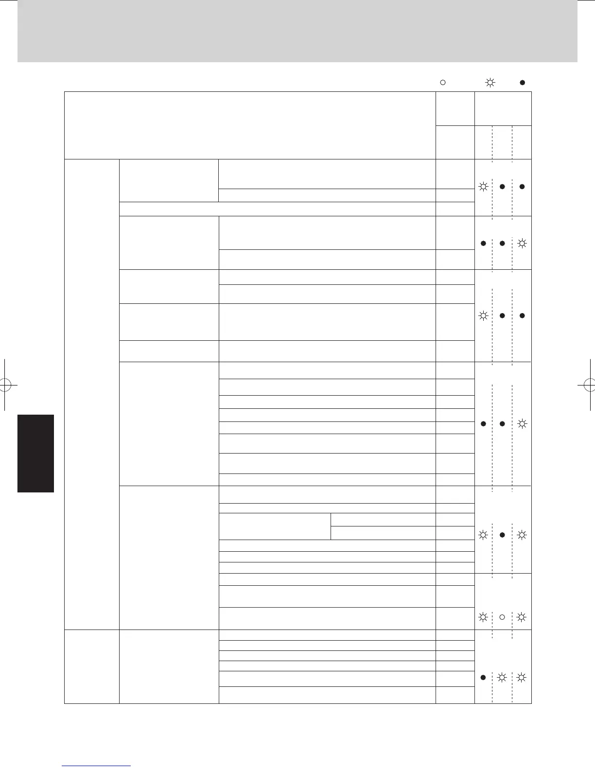
1. Contents of Remote Controller Switch Alarm Display
Mini VRF SYSTEM
Trouble Diagnosis
1. Contents of Remote Controller Switch Alarm Display
Remote controller is
detecting error signal from
indoor unit.
Indoor unit is detecting error
signal from outdoor unit.
Improper setting of indoor unit
or remote controller
.
During auto address setting,
number of connected units
does not correspond to
number set.
When turning on the power
supply, number of connected
units does not correspond to
number set.
(Except R.C. address is “0.”)
Indoor unit communication
error of group control wiring
Improper setting
<E01>
<E02>
<E06>
<<E03>>
E04
E08
<<E09>>
E12
E15
E16
E24
E26
E29
E30
E25
E18
<L03>
L04
L05
L06
L07
L08
<<L09>>
Indoor unit is detecting error signal from remote controller (and system controller).
Error in receiving serial communication signal
(Signal from main indoor unit in case of group control)
Ex: Auto address is not completed.
Error in transmitting serial communication signal
Error in receiving serial communication signal
When turning on the power supply, the number of connected
indoor units does not correspond to the number set. (Except R.C.
address is “0.”)
Indoor unit address setting is duplicated.
Remote controller address connector (RCU. ADR) is duplicated.
(Duplication of main remote controller)
Starting auto address setting is prohibited.
This alarm message shows that the auto address connector
CN-A.ADD is shorted while other RC line is executing auto
address operation.
Error in auto address setting (Number of connected indoor units
is less than the number set.)
Error in auto address setting (Number of connected indoor units
is more than the number set.)
Error of outdoor unit address setting
The number of connected main and sub outdoor units do not
correspond to the number set at main outdoor unit PCB.
Error of sub outdoor unit in receiving serial communication
signal from main outdoor unit
Outdoor unit serial communications failure.
Error of main indoor unit in receiving serial communication signal
from sub indoor units
Duplication of main indoor unit address setting in group control
Duplication of outdoor R.C. address setting
Group control wiring is connected to individual control indoor unit.
Indoor unit address is not set.
Capacity code of indoor unit is not set.
There are 2 or more indoor units
controllers which have operation
mode priority in 1 refrigerant circuit.
Priority set remote controller
Non-priority set remote controller
Error of the outdoor unit in receiving serial communication signal
from the indoor unit
No indoor unit is connected during auto address setting.
Main outdoor unit is detecting error signal from sub outdoor unit.
Serial
communication
errors
Missetting
Protective device in indoor
unit is activated.
<<P01>>
<<P09>>
<<P11>>
<<P10>>
<<P12>>
Thermal protector in indoor unit fan motor is activated.
Improper wiring connections of ceiling panel
Faulty drain pump. Drain pump locked.
Float switch is activated.
Operation of protective function of fan inverter
Activation of
protective
device
Continued
This alarm message shows when the indoor unit for multiple-use is
not connected to the outdoor unit.
Capacity code of outdoor unit is not set.
L02
L10
L18
4-way valve operation failure
Operation
Standby
for heating
Possible cause of malfunction
Wireless
remote controller
receiver display
Wired
remote
control
display
Timer
E20
Operating lamp
blinking
Operating lamp
blinking
Heating ready
lamp blinking
Heating ready
lamp blinking
Operating and
heating ready
lamps blinking
simultaneously
Operating and
heating ready
lamps blinking
simultaneously
Timer and heat
ready lamp
blinking
altemately
P14
Operation of O
2
sensor
Mini VRF SYSTEM
Trouble Diagnosis
1. Contents of Remote Controller Switch Alarm Display
ON: Blinking: OFF:
Possible cause of malfunction
Activation of
protective
device
Thermistor
fault
EEPROM on indoor unit PCB failure
Protective
device for
compressor is
activated
Protective device for
compressor is activated.
Protective device in outdoor
unit is activated.
Indoor thermistor is either
open or damaged.
Outdoor thermistor is either
open or damaged.
High-pressure switch
Incorrect discharge temperature (Comp.)
Power supply circuit failure, missing-phase detection
There is a trouble with the outdoor unit when the liquid valve
and the gas valve are closed.
Outdoor unit fan motor is unusual.
Compressor running failure resulting from missing phase in the
compressor wiring, etc. (Start failure not caused by IPM or no gas.)
Missing-phase/reverse-phase in the compressor wiring,
Compressor start-up failure (Overcurrent at time of INV
compressor starts up, etc.)
IPM trip (IPM current or temperature)
Indoor coil temp. sensor (E1)
Indoor coil temp. sensor (E3)
Indoor suction air (room) temp. sensor (TA)
Indoor discharge air temp. sensor (BL)
Comp. discharge gas temp. sensor (TD)
Outdoor coil liquid temp. sensor (C1)
Outdoor air temp. sensor (TO)
Compressor intake port temperature sensor (TS)
High pressure sensor
EEPROM on the outdoor unit PCB has failed.
Power supply current (CT) sensor failure
(Current is not detected at time of compressor ON.)
Overcurrent of power supply current (CT) sensor
PAM failure
P13
P05
P04
P03
P16
P22
P29
H31
<<F01>>
<<F03>>
<<F10>>
<<F11>>
F04
F07
F08
F12
F16
F29
F31
H03
H02
H01
Operation
Standby
for heating
Wired
remote
control
display
Wireless
remote controller
receiver display
Timer
Serial
Timer lamp blinking
Timer lamp blinking
Operating and
timer lamp blinking
simultaneously
Operating and
timer lamp blinking
simultaneously
Operating and
heating ready
lamp blinking
altemately
Operating and
timer lamps
blinking alternately
Operating and
timer lamps
blinking alternately
SM830195-04_Mini VRF SYS.indb 2 15/02/16 18:01:23
 Loading...