1 - 6
1
Mini VRF SYSTEM
Control Functions
2. Compressor Control
Mini VRF SYSTEM
Control Functions
2. Compressor Control
(2) Primary Current Protection
The primary current protection value is divided into the cooling and heating mode.
Also, the cooling of single-phase outdoor unit can be divided into two tables according to the outdoor air
temperature. 3-phase outdoor unit has no distinction for outdoor air temperature.
(3) Secondary Current Protection (Common to cooling & heating mode)
Regardless of the outdoor air temperature, the value of the primary current protection is controlled by the
contents of the table listed below.
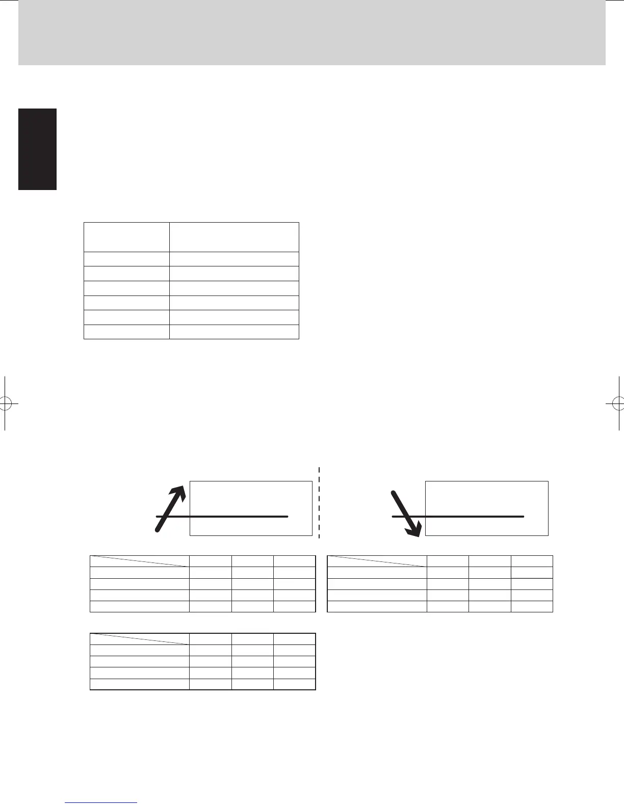
Concept view of outdoor air temperature
Table 1
unit : Amp. unit : Amp.
Single-phase Model
3-phase Model
Single-phase Model
3-phase Model
<Cooling>
Stop*1
Down*2
Not up*3
When outdoor air temperature increases : When outdoor air temperature decreases :
43.0°C
Outdoor air
temperature:
Cooling at Table 2
Section of outdoor air temp.
Cooling at Table 1
42.0°C
Outdoor air
temperature:
Cooling at Table 2
Section of outdoor air temp.
Cooling at Table 1
Followed by normal control
Table 2
4 hp
20.0~22.0
19.0~20.0
~19.0
22.0~
5 hp
23.0~25.0
22.0~23.0
~22.0
25.0~
6 hp
26.0~28.0
25.0~26.0
~25.0
28.0~
Stop*1
Down*2
Not up*3
Followed by normal control
4 hp
20.0~22.0
19.0~20.0
~19.0
22.0~
5 hp
23.0~25.0
22.0~23.0
~22.0
25.0~
6 hp
24.0~28.0
23.0~24.0
~23.0
28.0~
Stop*1
Down*2
Not up*3
Followed by normal control
4 hp
21.0~23.0
20.0~21.0
~20.0
23.0~
5 hp
24.5~26.5
23.5~24.5
~23.5
26.5~
6 hp
28.0~30.0
27.0~28.0
~27.0
30.0~
hp : horsepowerhp : horsepower
hp : horsepower
unit : Amp.
3-phase Model
Stop*1
Down*2
Not up*3
Followed by normal control
4 hp
8.5~10.5
7.5~8.5
~7.5
10.5~
5 hp
10.0~12.0
9.0~10.0
~9.0
12.0~
6 hp
12.0~14.0
11.0~12.0
~11.0
14.0~
hp : horsepower
unit : Amp. hp : horsepower
Stop*1
Down*2
Not up*3
Followed by normal control
unit : Amp. hp : horsepower
Stop*1
Down*2
Not up*3
Followed by normal control
Common to 4/5/6 hp
21.0~24.0
20.0~21.0
~20.0
24.0~
Common to 4/5/6 hp
15.0~18.0
14.0~15.0
~14.0
18.0~
Each value shown in the table indicates the detected value.
When the detected value is detected as shown in the table :
*1
*2
*3
Stop the compressor.
Decrease the frequency that the compressor is controlled.
Do not increase the frequency that the compressor is
controlled.
NOTE
Each value shown in the table indicates the detected value.
When the detected value is detected as shown in the table :
*1
*2
Stop the compressor.
Decrease the frequency that the compressor is controlled.
*3 Do not increase the frequency that the compressor is
controlled.
NOTE
unit : Amp.
Stop*1
Down*2
Not up*3
Followed by normal control
4 hp
8.5~10.5
7.5~8.5
~7.5
10.5~
5 hp
10.0~12.0
9.0~10.0
~9.0
12.0~
6 hp
12.0~14.0
11.0~12.0
~11.0
14.0~
hp : horsepower
Horsepower (hp) limits
+2 hp down
+1 hp down
+0.5 hp down
Hp increase prohibited
Hp increase permitted (slowly)
No restriction
105
104
102
99 – Less than 102
96 – Less than 99
Less than 96
The values shown in the table above are reduced to the
values calculated by roadmap control.
Air discharge
temperature level
2-3-2. Roadmap control in heating mode
Roadmap control is performed using the below condensation temperature control.
Horsepower increase prohibited
Horsepower decrease
Horsepower increase permitted
Thermostat OFF
57.5°C
57.4°C
51.6°C
51.5°C
49.0°C
48.9°C
(Area D)
(Area C)
(Area B)
(Area A)
(1)
(2)
(3)
(4)
*
(1)
Condensation temperature (=Tc) control
Fig. 1-3
For indoor units that are operating in Heating mode, if one unit is selected for a test run, the air intake temper-
ature difference is ignored;however, Tc control is performed according to Fig.1-3 in order to prevent excessive
load.(This is used for test run checks, etc.)
Even within the same area, the compressor capacity varies depending on the refrigerant temperature.
If the condensation temperature (Tc) enters area D and the thermostat turns OFF, the next time the compres-
sor starts it may restart from a lower capacity.
When the area changes to area C, area C is considered to be area B for control purposes for the first 6 min-
utes, even if the horsepower is the minimum value within the range where capacity control is possible (opera-
tion with inverter frequency of 25 Hz only). Subsequently if C area continues, the thermostat turns OFF.
2-3-4. Protection control
Protection control consists of 2 types of protection:compressor air discharge temperature protection and current
protection. The limit values from this protection control are incorporated into the output compressor capacity
increase/decrease values that were calculated from roadmap control.
In some cases, the control shown below may stop the compressor, issue an alarm, or reduce the compressor
capacity.
Air discharge temperature protection
The compressor capacity is limited by using the air discharge temperature of the operating compressor (as
shown in the tables below).
(Air discharge temperature level:Highest level among the air discharge temperature levels of all compressors)
SM830195-04_Mini VRF SYS.indb 6 15/03/10 17:47:32
 Loading...