Mini VRF SYSTEM
Remote Controller Functions
4
4
4 - 11
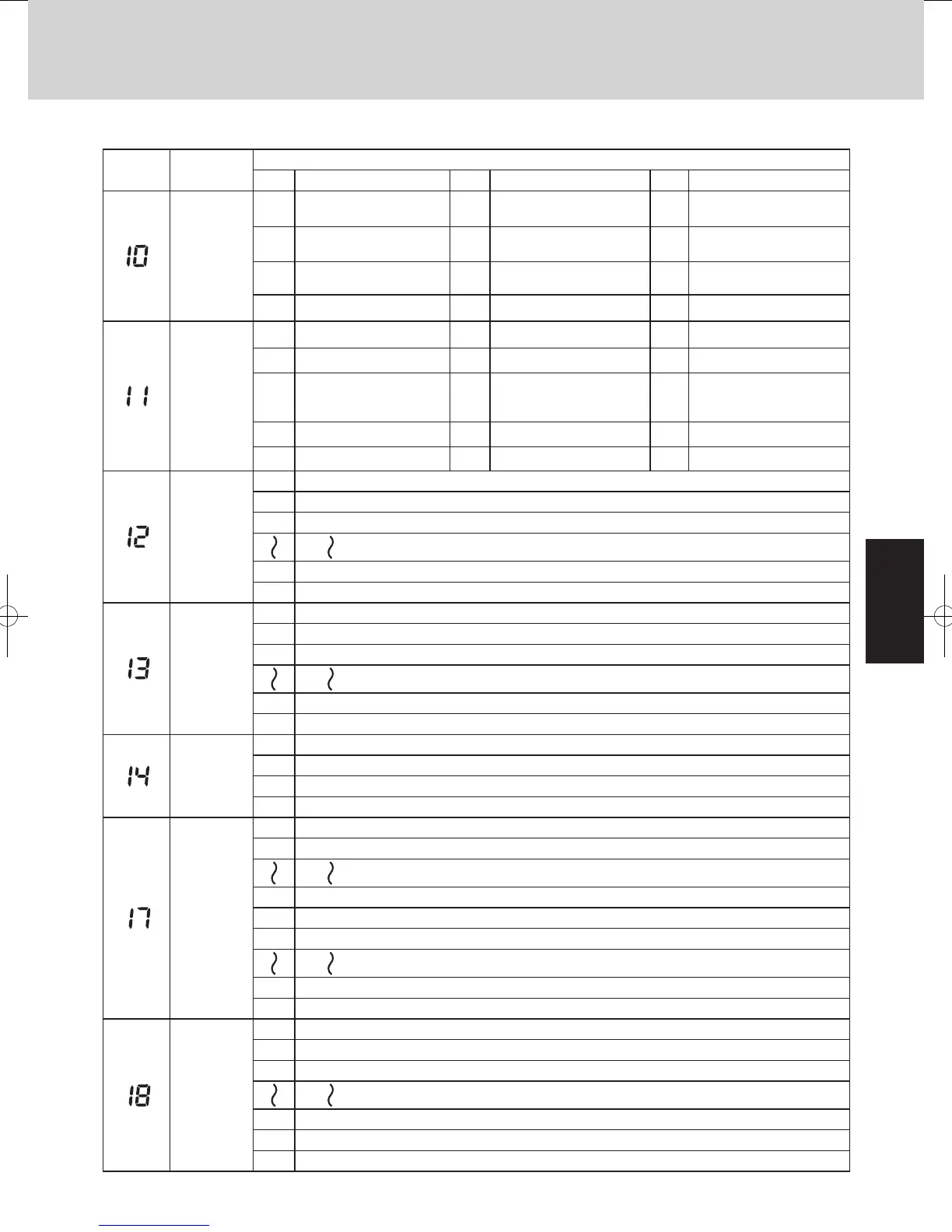
2. Detailed Settings Function
List of Detailed Setting Items
Item code Item
Setting data
No. Description No. Description No. Description
Type
0001
4-Way Cassette (60×60)
(U1, Y1, Y2)
0002 2-Way Cassette (L1) 0003 1-Way Cassette (D1)
0005
Low Silhouette Ducted (F1, F2)
Slim Low Static Ducted (M1)
0006
High Static Pressure
Ducted (E1)
0007 Ceiling (T1)
0008 Wall Mounted (K1, K2) 0010 Floor Standing (P1) 0011
Concealed Floor
Standing (R1)
0037 Slim Type Ducted (Z1)
Indoor unit
capacity
0038 15 (Type 15) 0001 22 (Type 22) 0003 28 (Type 28)
0005 36 (Type 36) 0007 45 (Type 45) 0009 56 (Type 56)
0010 63 (Type 60) 0011
71 (Type 73)
For S-71MP1E5
and S-71MR1E5
0012
80 (Type 73)
Except S-71MP1E5
and S-71MR1E5
0013 90 (Type 90) 0015 112 (Type 106) 0017 140 (Type 140)
0018 160 (Type 160)
System
address
0001 Unit No. 1
0002 Unit No. 2
0003 Unit No. 3
0030 Unit No. 30
0099 Not set
Indoor unit
address
0001 Unit No. 1
0002 Unit No. 2
0003 Unit No. 3
0064 Unit No. 64
0099 Not set
Group control
address
0000 Individual (1:1 = Indoor unit with no group wiring)
0001 Main unit (One of the group-control indoor units)
0002 Sub unit (All group-control indoor units except for main unit)
0099 Not set
Cooling
intake
temperature
shift
–010 Shifts intake temperature by –10°C.
–009 Shifts intake temperature by –9°C.
–001 Shifts intake temperature by –1°C.
0000 No intake temperature shift
0001 Shifts intake temperature by +1°C.
0009 Shifts intake temperature by +9°C.
0010 Shifts intake temperature by +10°C.
Automatic
stop time
after
operation
start
0000 Function disabled
0001 Stops automatically 5 minutes after operation starts.
0002 Stops automatically 10 minutes after operation starts.
* Can be set
in 5-minute
units.
0123 Stops automatically 615 minutes after operation starts.
0124 Stops automatically 620 minutes after operation starts.
0125 Stops automatically 625 minutes after operation starts.
<Procedure of CZ-RTC3>
CZ-RTC3
Fig. 4-5
1
Keep pressing the , and
buttons
simultaneously for 4 or more seconds.
The “Maintenance func” screen appears on the
LCD display.
2
Press the or button to see each
menu.
If you wish to see the next screen instantly, press
the or button.
Select “8. Detailed settings” on the LCD display
and press the button.
The “Detailed settings” screen appears on the
LCD display.
Select the “Unit no.” by pressing the or
button for changes.
Maintenance func
1. Outdoor unit error data
2. Service contact
3. RC setting mode
4.Test run
Sel. Page [ ] Confirm
20:30 (THU)
Maintenance func
5. Sensor info.
6. Servicing check
8. Detailed settings
Sel. Page [ ] Confirm
20:30 (THU)
7. Simple settings
Detailed settings
Unit no. Code no. Set data
103-1 0001
Sel. Next
20:30 (THU)
3
Select the “Code no.” by pressing the or
button.
Change the “Code no.” by pressing the or
button (or keeping it pressed).
4
Select the “Set data” by pressing the or
button.
Select one of the “Set data” by pressing the
or button.
Then press the button.
5
Select the “Unit no.” by pressing the or
button and press the button.
The “Exit detailed settings and restart?” (Detailed
setting-end) screen appears on the LCD display.
Select “YES” and press the button.
Detailed settings
Unit no. Code no. Set data
3-1 0001
Sel. Next
20:30 (THU)
10
Detailed settings
Unit no. Code no. Set data
3-1
Sel.
20:30 (THU)
10 0001
Detailed settings
Unit no. Code no. Set data
ALL
Sel. Next
20:30 (THU)
01 0002
Exit detailed settings
and restart?
NOYES
SM830231-00Single欧州.indb6 2014/04/0413:48:32
START
[ ]
20:30 (THU)
[ ] Confirm
SM830195-04_Mini VRF SYS.indb 11 15/02/16 17:59:52
 Loading...