Mini VRF SYSTEM
Remote Controller Functions
4
4 - 20
2. Detailed Settings Function
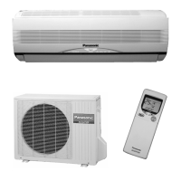
Selecting the DC fan motor tap (when setting from the PCB)
1-Way Cassette type
<Procedure> Be sure to turn OFF the main power source before performing the steps below.
Open the electrical component box cover, then check the indoor unit control PCB. (Fig. 4-7)
Connect the jumper connector (2P: yellow) which was supplied with the accessory to the correct connector pin on
the indoor unit control PCB according to the setting number which was confirmed in “ List of Detailed Setting
Items ” (Item code 5d).
When using with the high ceiling settings
Connect the jumper connector to the connector pin TP1 (2P: red) on the indoor unit control PCB.
When using with the discharge grille (purchased separately) attached (2-way lowered ceiling system)
Connect the jumper connector to the connector pin TP3 (2P: yellow) on the indoor unit control PCB.
TP6
White Yellow
Red
TP3 TP1
Fig. 4-7
4-Way Cassette type
<Procedure> Stop the system before performing these steps.
Open the electrical component box cover, then check the indoor unit control PCB.
Setting No. (3) :
Setting No. (6) :
Connect the jumper connector (2P: yellow) which was supplied with the accessory to the correct connector pin
on the indoor unit control PCB according to the setting number which was confirmed in Ta ble 1 for DC Fan Motor
Tap Settings.
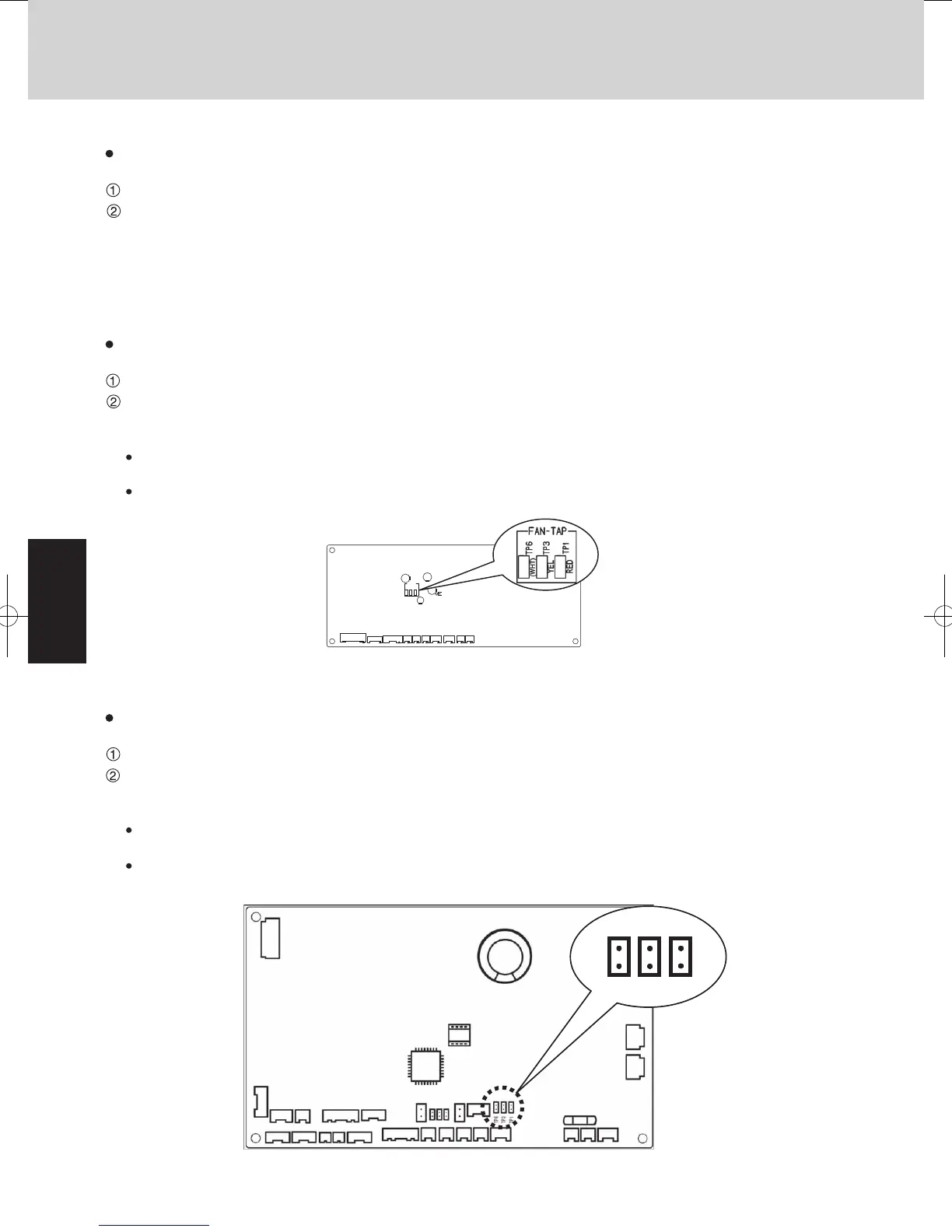
Ceiling type
<Procedure> Stop the system before performing these steps.
Open the electrical component box cover, then check the indoor unit control PCB. (Fig. 4-6)
Connect the jumper connector (2P: yellow) which was supplied with the accessory to the correct connector pin on
the indoor unit control PCB according to the setting number which was confirmed in Ta ble 2 (Table of DC Fan
Motor Tap Settings).
If the setting No. is (1), then connect the jumper connector to the connector pin TP1 (2P: red) on the indoor unit con-
trol PCB.
If the setting No. is (3), then connect the jumper connector to the connector pin TP3 (2P: yellow) on the indoor unit
control PCB.
Then connect the jumper connector to the connector pin TP3 (2P: yellow) on the indoor unit control PCB.
Then connect the jumper connector to the connector pin TP6 (2P: white) on the indoor unit control PCB.
Fig. 4-6
FAN-TAP
TP6
TP3
TP1
(WHT)
YEL
RED
2WAY SYSTEM
Remote Controller Functions
3. Remote Controller Servicing Functions
The remote controller includes a number of servicing functions. Use these as needed for test runs and
inspections.
List of Servicing Functions
< Function of CZ-RTC2 >
Functions Description Button operation Reset operation Unit status
Test run
Operation with
forced thermostat
ON
Press and hold the
button
for 4 seconds or longer.
Press the
button.
Current operation is
maintained.
Sensor
temperature
display
Temperature
display from each
sensor
Press and hold the
and
buttons for 4 seconds or
longer.
Servicing check
display
Alarm history
display
Press and hold the
and
buttons for 4 seconds or
longer.
Simple settings
Filter life time,
operating mode
priority, central
control address,
and other settings
Press and hold the
and
buttons for 4 seconds or
longer.
When settings are made
from a remote controller,
the indoor unit where that
remote controller is
connected stops.
Detailed settings
System address,
indoor unit address,
central control
address, and other
settings
Press and hold the
,
and buttons for 4 seconds
or longer.
Automatic
address
Automatic address
setting based on
command from
the wired remote
controller
Press and hold the
and
the timer operation
buttons
for 4 seconds or longer.
Automatic reset
Entire system stops.
Address change
Change of indoor
unit address
Press and hold the
and
the timer operation
buttons
for 4 seconds or longer.
Press the
button.
•
Fig. 4-8
SM830195-04_Mini VRF SYS.indb 20 15/02/16 17:59:55
 Loading...