Mini VRF SYSTEM
Remote Controller Functions
4
4 - 26
3. Remote Controller Servicing Functions
Mini VRF SYSTEM
Remote Controller Functions
3. Remote Controller Servicing Functions
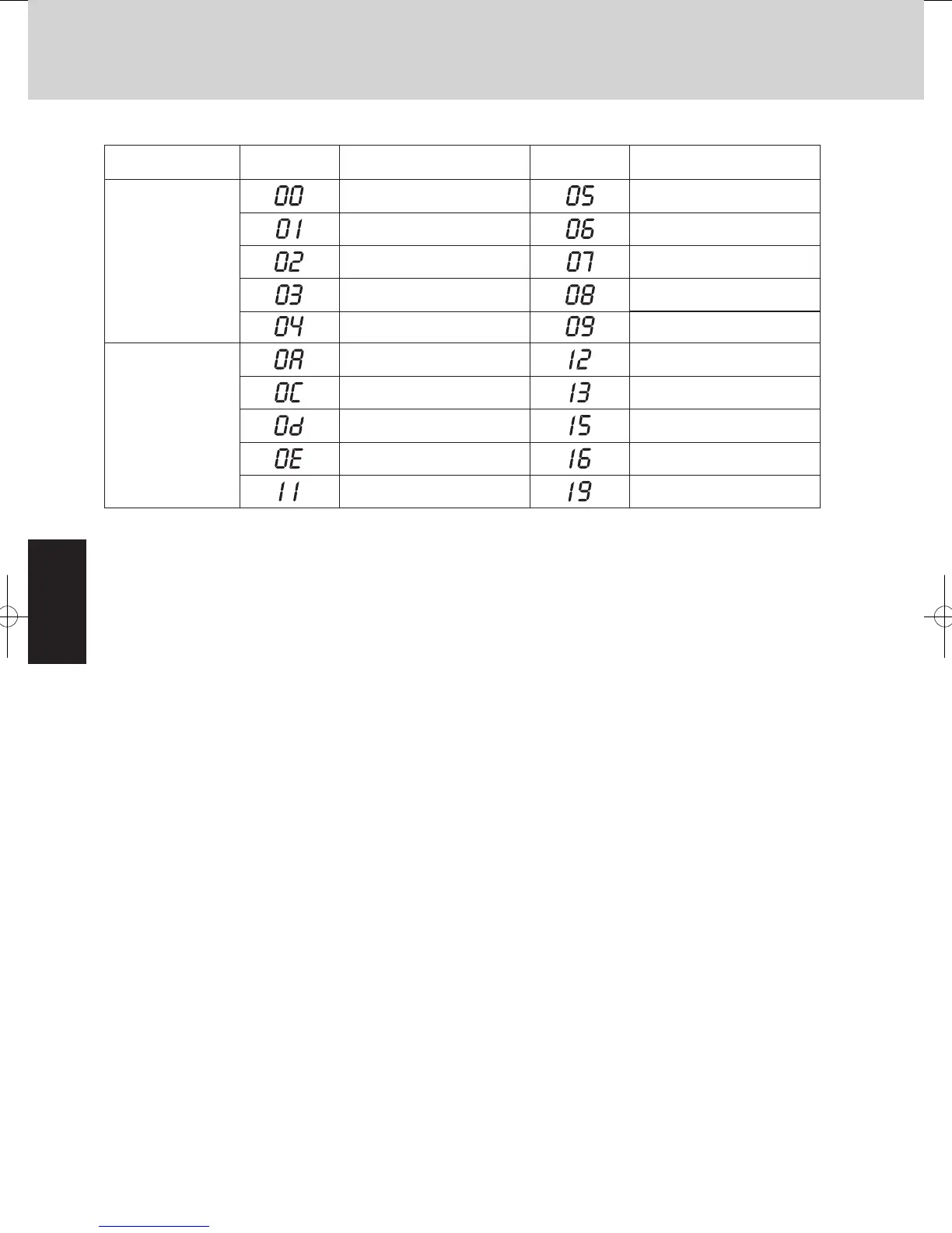
Location where
sensor is installed
Sensor
address
Sensor typeSensor type
Indoor unit
Indoor unit intake
temp. (TA)
Indoor unit heat exchanger
temp. E1 (E1)
Heat exchanger liquid (C1)
—
Indoor unit heat exchanger
temp. E3 (E3)
Discharge air temp. (BL)
Discharge air temp. setting
Indoor unit MOV pulse (MOV)
—
Outdoor unit
High-pressure sensor
temp.
Suction temp. (TS)
Outdoor air temp.
Inverter primary current
—
—
Sensor Temperature Relationship Table
Room temp. controlled*
Remote controller
temp.
Discharge temp. (TD)
Sensor
address
MOV pulse (MOV)
Actual operating Frequency
*Room temp. controlled: = Controlled room temperature
•When body thermostat controlled:
Controlled room temperature = Indoor unit intake temp. (TA) – Intake temperature shift (*1)
•Remote control thermostat controlled:
Controlled room temperature = Remote controller temp.
*1 Intake temperature shift: This is the shift value considered the temperature difference between the upper area
and lower area of the room in heating mode.
It is the value of the code “06” in the indoor unit’s EEPROM settings.
Cooling mode: = 0
SM830195-04_Mini VRF SYS.indb 26 15/02/16 17:59:56
 Loading...