DISASSEMBLY / REASSEMBLY INSTRUCTIONS
Issue 1 Section 4 MCUK000601C8
Revision 0 – 20 – Service Manual
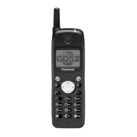
Figure 4.2: GD52 Battery Removal
3. Remove the four case screws located inside the battery compartment.
Figure 4.3: GD52 Case Screw Removal
4. Remove the cover from the case by pulling from the connector end of the telephone. Care must be taken when separating
the case from the cover as the retaining clips may be very stiff - if necessary, re-attach the battery cover to provide extra
support for the case.
Figure 4.4: GD52 Case-Cover Separation
5. Remove the PCB assembly from the cover.
10235-1
10234-1
10236-1
 Loading...