13
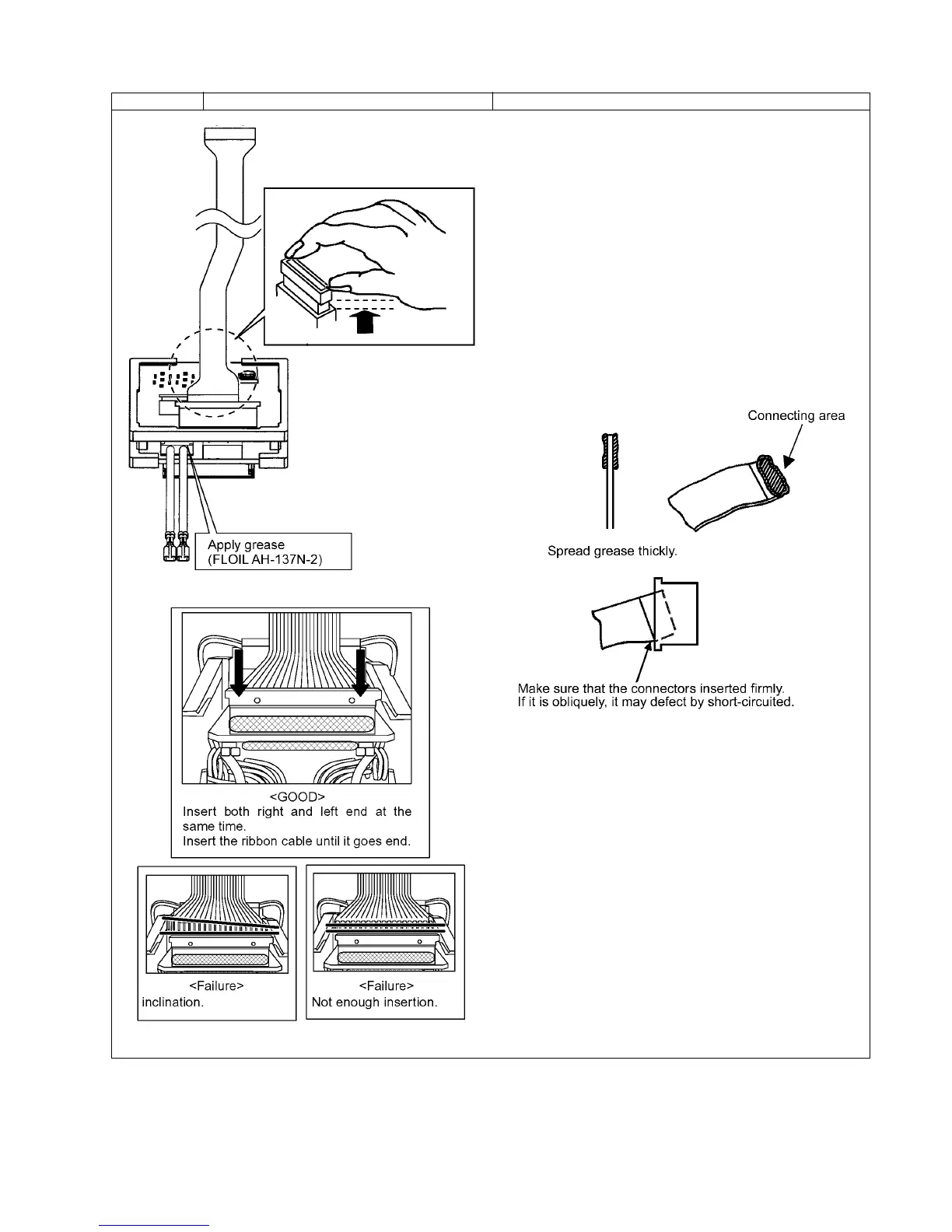
Ref. No. 2C Procedure 2A 2B 2C Assembly of Switch and Motor assembly.
1. Attach the quick connect terminal of the white lead wire from the
motor stator with the switch assembly (M+).
2. Apply grease (FLOIL AH-137N-2 / WEWGW2) on the both side and
both end of ribbon cable where insert into the connectors.
NOTE:
Confirm if there is no dust or any foreign substances.
3. Slightly lift the connector up.
NOTE:
Do not pull the connector forcefully. It does not separate from the
other connector.
4. Insert the ribbon cable into the motor stator and the main PCB.
NOTE:
Make sure to handle the ribbon cable gently in order to avoid the
breakage.
5. Insert the quick connect terminal of motor lead wire (black) into the (-)
side of terminal block.
6. Insert the connector of harness into the main PCB.
7. Connect the black lead wire into the (-) side of terminal block and the
read lead wire goes to (+) side of terminal block.
 Loading...