Basic Instructions
2 − 41
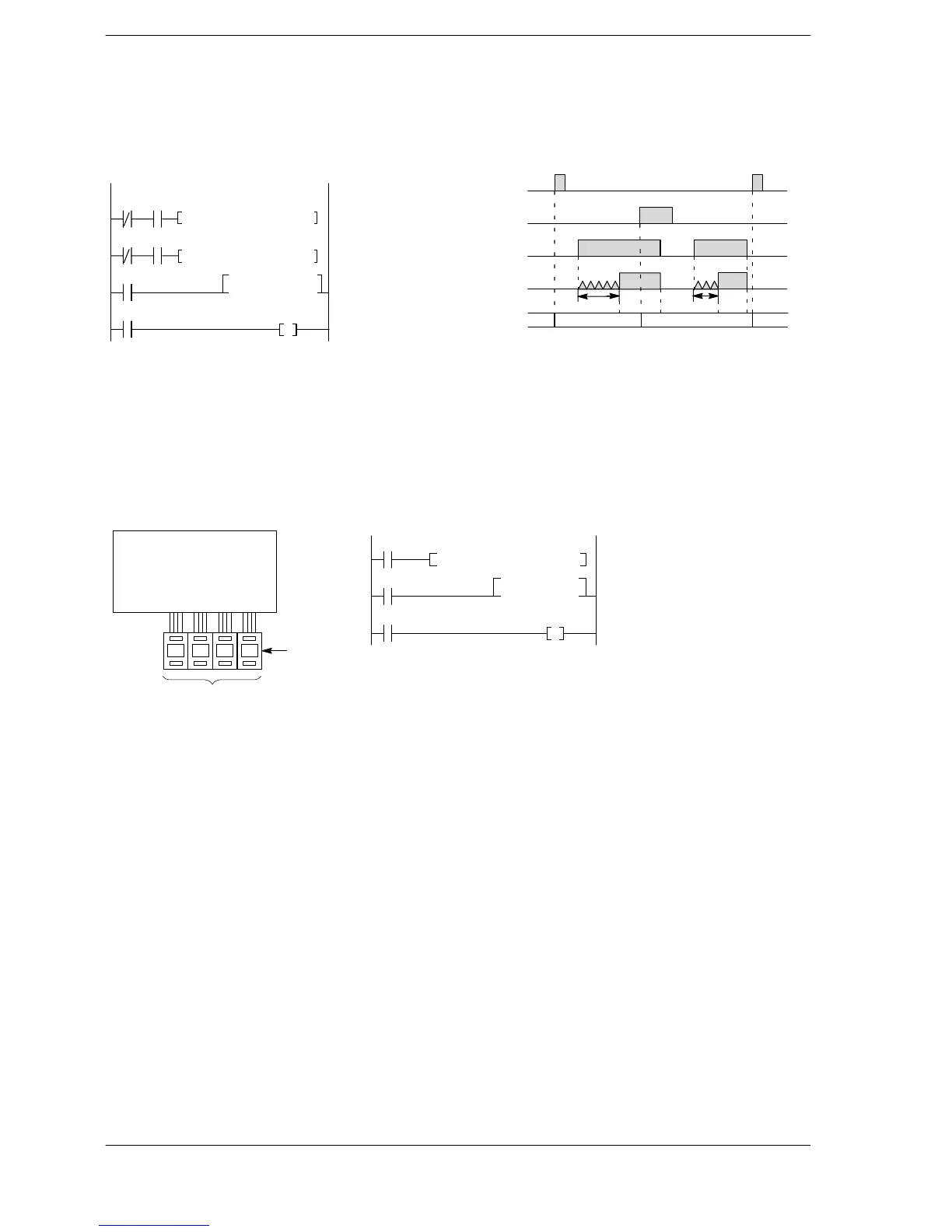
Changing set values based on specified conditions
The set value is K50 when X0 is on and K30 when X1 is on.
Ladder diagram Boolean Time chart
T5
X2
Y30
ST/ X 1
AN X 0
F0 (MV)
K 500
DT 0
ST/ X 0
AN X 1
F0 (MV)
K 300
DT 0
ST X 2
TML 5
DT 0
ST T 5
OT Y 30
X0
X1
X2
0.5s
T5
X0 X1
X1 X0
0.3s
DT0
K0 K500 K300 K500
on
off
on
off
on
off
on
off
F0 MV, K 500, DT 0
F0 MV, K 300, DT 0
TML 5, DT 0
Example of setting a set value from external digital switches
The BCD data of the digital switches connected to X0 through XF is converted and becomes the set value
T5
R11
TML 5,
DT 1
Y30
ST R 10
F81 (BIN)
WX 0
DT 1
ST R 11
TML 5
DT 1
ST T 5
OT Y 30
R10
F81BIN,WX0,DT1
CPU and input units
0 7 9 4
WX0
Digital switch
Set value
of timer
Connection example Ladder diagram Boolean
 Loading...


