Basic Instructions
2 − 55
Description
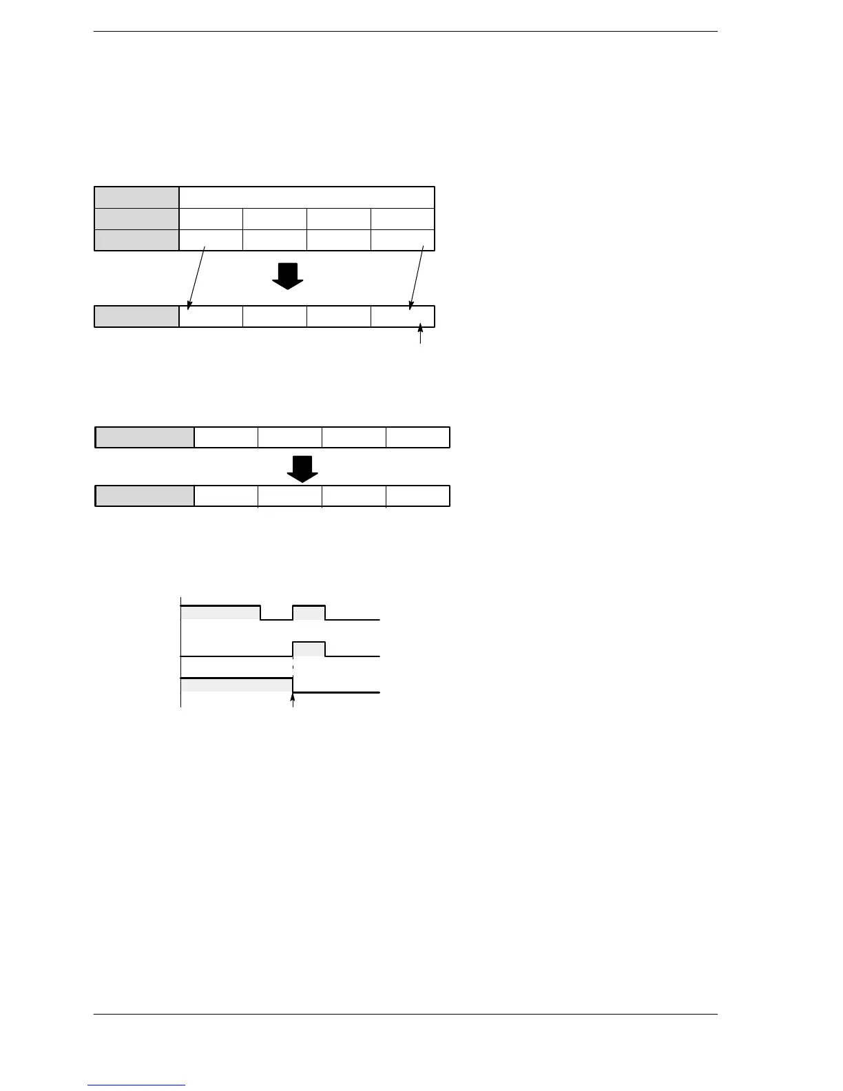
Shifts the specified data area (WR) one bit to the left.
When the shift input turns on (rises), the contents of WR are shifted one bit to the left.
During the shift, 1 is set in the empty bit (least significant bit) if the data input is on, or 0 if the data input is off.
When shift input is turned on:
WR3
Bit position
Binary data
3F 30
................
15
..
12 11
..
87
..
43
..
0
0000 1000 1000 1100
Binary data
0001 0001 0001 1000
Data input (X0) on: set bit to 1.
Data input (X0) off: set bit to 0.
Shifts one bit
to the left.
When the reset input turns on, the contents of WR are cleared.
When reset input is turned on:
WR (Binary data)
0011 0100 0001 1001
0000 0000 0000 0000
Contents of WR3 are
cleared to 0.
WR (Binary data)
Precautions during programming
The SR instruction needs data input, a shift input, and a reset input.
When the reset input and the shift input are detected simultaneously, the reset input has priority.
Reset input
Data area (Rn)
Reset input is given priority
Shift input
If the internal relay area is specified as a hold type, take care that the data in the area is not reset to “0” when
the power turns on.
When combining a shift register instruction with an ANS or POPS instruction, take care that the syntax is
correct.
 Loading...


