EasyManua.ls Logo

Panasonic FP-E - Page 164

Panasonic FP-E
1334 pages
Print Icon
To Next Page IconTo Next Page
To Previous Page IconTo Previous Page
Loading...
Basic Instructions
2 54
Outline One bit shift of 16-bit [word internal relay (WR)] data to the left.
5
Program example
Ladder
Diagram
Boolean
Ladder Diagram
Address Instruction
X1
SR WR 3
X0
0
Data input
1
X2
Reset input
2
Shift input
D
0
1
2
3
ST X 0
ST X 1
ST X 2
SR WR 3
Operands
Instruction
Relay Timer/Counter Register
Index
register
Constant
Index
modifier
Instruction
WX WY WR WL SV EV DT LD FL IX IY K H
modifier
(*)
D: Data area N/A N/A A N/A N/A N/A N/A N/A N/A N/A N/A N/A N/A A
(*) This can be used only with the FP2/FP2SH/FP10SH.
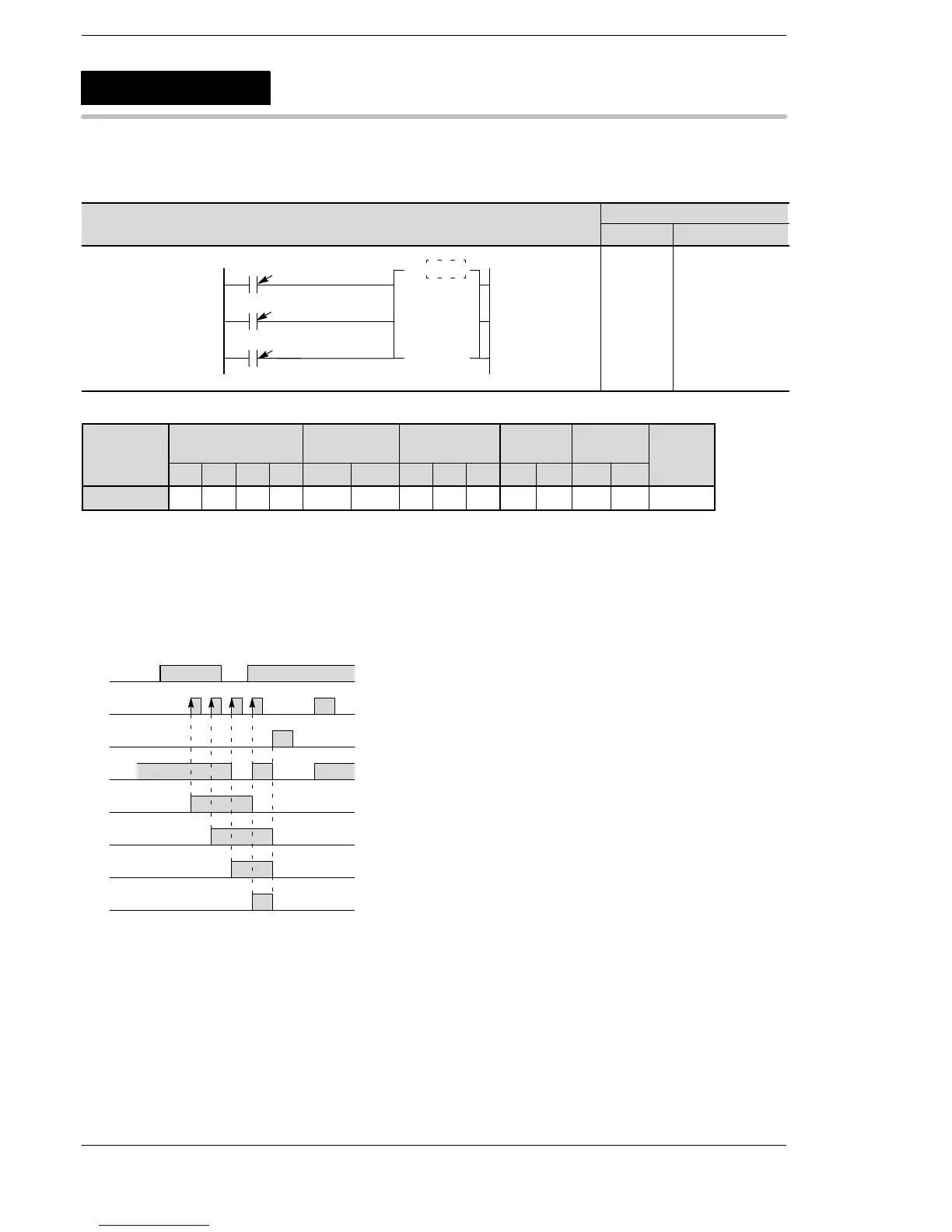
Explanation of example
If the X1 turns on when X2 is in the off state, the contents of the internal relay WR3 (internal relays R30 to R3F)
are shifted one bit to the left.
“1” is shifted in R30 if X0 is on, and “0” is shifted in R30 if X0 is off.
If the X2 turns on, the contents of WR3 are reset to 0.
X0
X1
X2
on
off
R30
on
off
R31
on
off
R32
on
off
R33
on
off
R34
on
off
on
off
on
off
SR
Shift register
A: Available
N/A: Not Available
Phone: 800.894.0412 - Fax: 888.723.4773 - Web: www.clrwtr.com - Email: info@clrwtr.com

Related product manuals