Boolean
Ladder Diagram
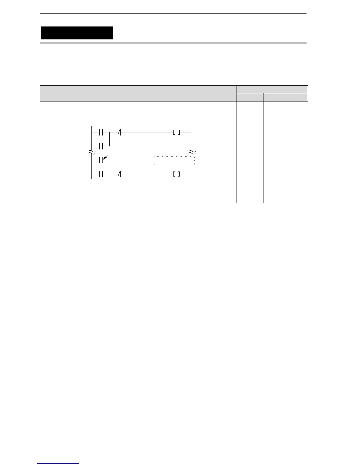
Address Instruction
0
X0
Y30
Y30X1
R0
Y31
96
X2
( CNDE )
98
X3
Execution condition (Trigger)
0
1
2
3
96
97
98
99
100
....
ST X 0
OR Y 30
AN/ X 1
OT Y 30
ST X 3
CNDE
ST R 0
AN/ X 2
OT Y 31
....
Description
The CNDE instruction enables you to end one scan of the program.
When the execution condition (trigger) turns on, the program finishes and the input, output, and other such
operations are performed. When the operations are completed, the program then returns to the starting
address.
You can adjust the timing that operations are performed by performing the operations only after a required
number of program scans are completed.
The CNDE instruction cannot be performed in sub−programs such as subroutine programs or interrupt
programs. Use the CNDE instruction in the main program area only.
Two or more CNDE instructions can be used within the main program.
You must be careful when using one of the instructions below, which are executed by detecting the leading
edge of a execution condition (trigger) such as the differential instruction.
− DF (leading edge differential)
− Count input for CT (counter)
− Count input for F118 (UDC) (up/down counter)
− Shift input for SR (shift register)
− Shift input for F119 (LRSR) (left/right shift register)
− NSTP (next step)
− Differential execution type high−level instruction (this instruction is specified by P and a number)
CNDE
Conditional end
 Loading...


