High−level Instructions
3 − 15
Explanation of example
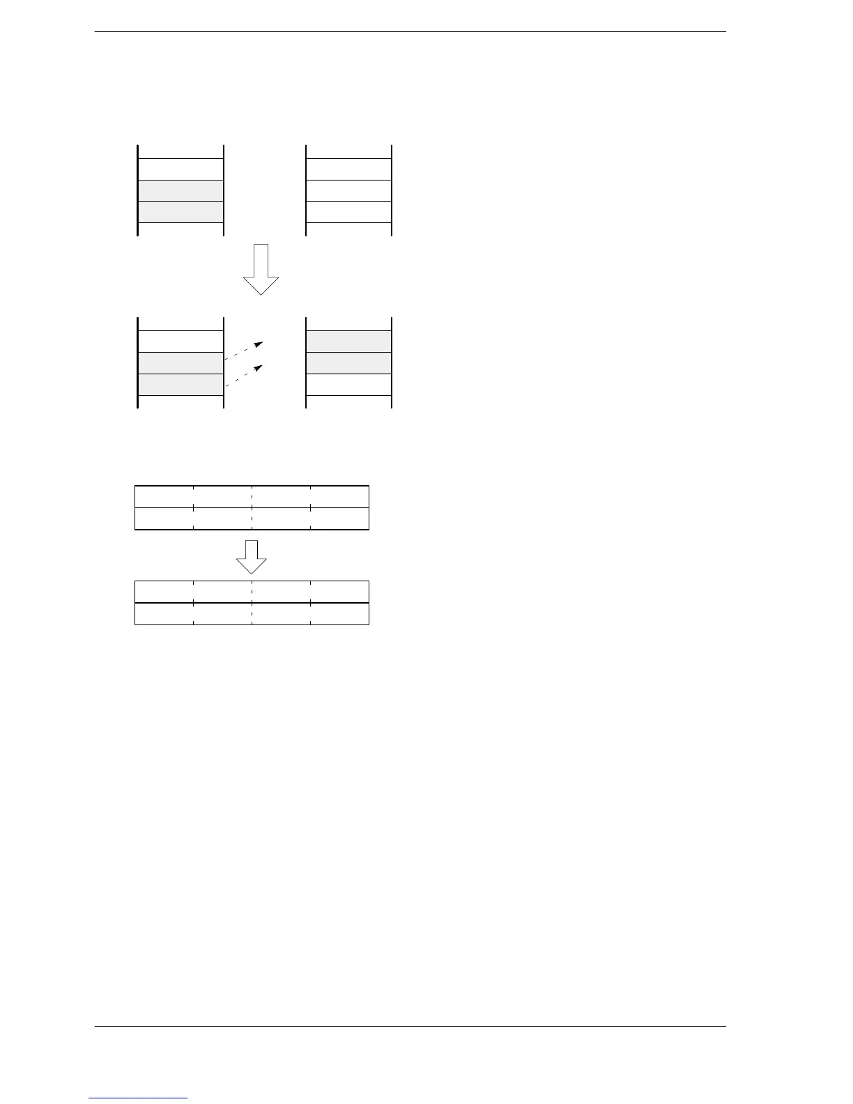
The contents of data registers DT12 and DT11 are inverted and transferred to data registers DT21 and DT20
when trigger R0 turns on.
Invert and
transfer
DT10
DT11
DT12
DT20
DT21
DT22
H 34AH0
H 25AC
H FFFD
[S]
H 1111
H FFFF
[D]
H2H0
H 25AC
H FFFD
DT10
DT11
DT12
[S]
H FFFF
H FFFF
DT20
DT21
DT22
[D]
R0: on
“F3 (DMV/)” execution
Description
The 32-bit data or 32-bit equivalent constant specified by S is inverted and transferred to the 32-bit area
specified by D.
1100 1101 0001 0101
S
S+1
0011 0010 1110 1010
D
D+1
0000 0111 0101 1011
1111 1000 1010 0100
When processing 32-bit data, the higher 16-bit areas (S+1, D+1) are automatically determined once the
lower 16-bit areas (S, D) are specified.
Flag conditions
・Error flag (R9007): Turns on and stays on when the area specified using the index modifier
exceeds the limit.
・Error flag (R9008): Turns on for an instant when the area specified using the index modifier
exceeds the limit.






 To Next Page