Relays, Memory Areas and Constants
1-8
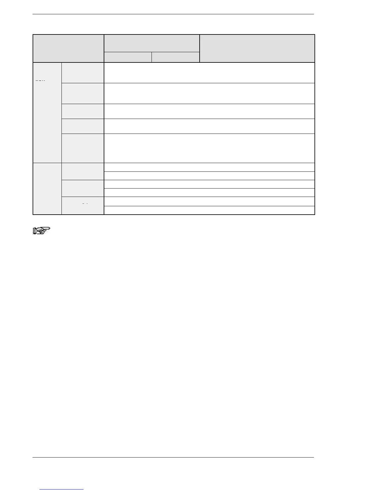
FunctionNumber of points and range of
memory area available for use
Item Function
C32, T32, F32C10, C14, C16
Item
Control
instruc-
tion
Master control
relay points
(MCR)
256 points
point
Number of
labels (JP and
LOOP)
256 points
Number of
step ladders
1000 stages
Number of
subroutines
500 subroutines
Number of
interrupt
programs
C10: 11 programs (6 external input points, 1 periodical interrupt point, 4−pulse match
points)
Other than C10: 13 programs (8 external input points, 1 periodical interrupt point,
4−pulse match points)
Constant Decimal
K−32, 768 to K32, 767 (for 16−bit operation)
constants (K)
K−2, 147, 483, 648 to K2, 147, 483, 647 (for 32−bit operation)
Hexadecimal
type (F)
F1.175494×10
−38
to F3.402823×10
38
Notes
1) The number of points noted above is the number reserved as
the calculation memory. The actual number of points available
for use is determined by the hardware configuration.
2) There are two types, one is the hold type that the last state is
stored even if the power supply turns off or the mode is
changed to PROG. mode from RUN mode, and the other is the
non−hold type that the state is reset.
For C10/C14/C16/C32: The hold type areas and non−hold type
areas are fixed. For information on the
sections of each area, refer to the
performance specifications.
For T32/F32: The settings of the hold type areas and
non−hold type areas can be changed using the
system registers.
On T32, if the battery has run out, the data in
the hold area may be indefinite (Not cleared to 0)
3) The points for the timer and counter can be changed by the
setting of system register 5. The number given in the table are
the numbers when system register 5 is at its default setting.