High−level Instructions
3 − 213
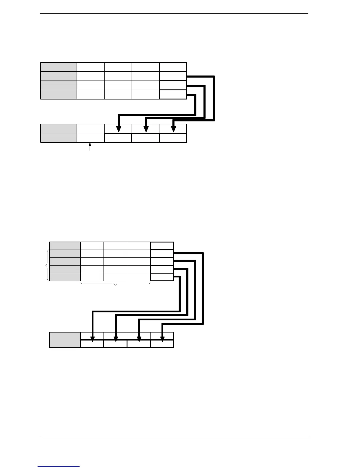
Explanation of example
Extracts lower 4 bits of data registers DT12 to DT10, combines the extracted data, and stores it in data
register DT20 when trigger R20 turns on.
····Bit position ·····
DT10
15
000
12
0
11
000
8
0
7
000
4
0
3
000
0
1
DT11
DT12
0000000000000100
0000000000000010
····
Bit position
·····
DT20
15
000
12
0
11
010
8
0
7
001
4
0
3
000
0
1
When the n < K4, “0” is set to bit position 12 to 15.
Description
Extracts the lower 4 bits (bit positions 0 to 3) of each specified area, starting from the 16-bit area specified by S
and combines the extracted data into one word. The result is stored in the 16-bit area specified by D.
n specifies the number of data areas to be extracted.
(range of n: K0 to K4)
When K0 is specified for n, this instruction is not executed.
When n < K4, “0” is automatically set to positions at D where the corresponding 16-bit source data does not
exist.
····
Bit position
·····
S
15 1211 8 7 4 3 0
Bit positions 4 to 15 of each
data area are invalid.
Destination
Source
S+1
S+2
····
Bit position
·····
D
15 1211 8 7 4 3 0
Digit 4 Digit 3 Digit 2 Digit 1
Digit 4
Digit 3
Digit 2
Digit 1
S+3
n
Flag conditions
・Error flag (R9007): Turns on and stays on when:
・Error flag (R9008): Turns on for an instant when:
− The area specified using the index modifier exceeds the limit.
− The number of data areas to be combined “n” is K5 or more.





 To Next Page