1.3 Explanation of Memory Areas
1-45
Non−hold type data and hold−type data
There are two types of data registers which handle data differently when the power is
turned off or the mode is changed from RUN to PROG.:
− Hold type data registers hold their contents while operation stops and allow
operation to be restarted with the contents still effective.
− Non−hold type data registers reset when operation stops.
For the FP0 C10/C14/C16/C32, and FP−e without clock/calendar function, non−hold
type and hold type data register numbers are as shown in the following table.
Item FP0 C10/C14/C16 and FP−e FP0 C32
Data register Non−hold type 1652 words (DT0 to DT1651) 6112 words (DT0 to DT6111)
Hold type 8 words (DT1652 to DT1659) 32 words (DT6112 to DT6143)
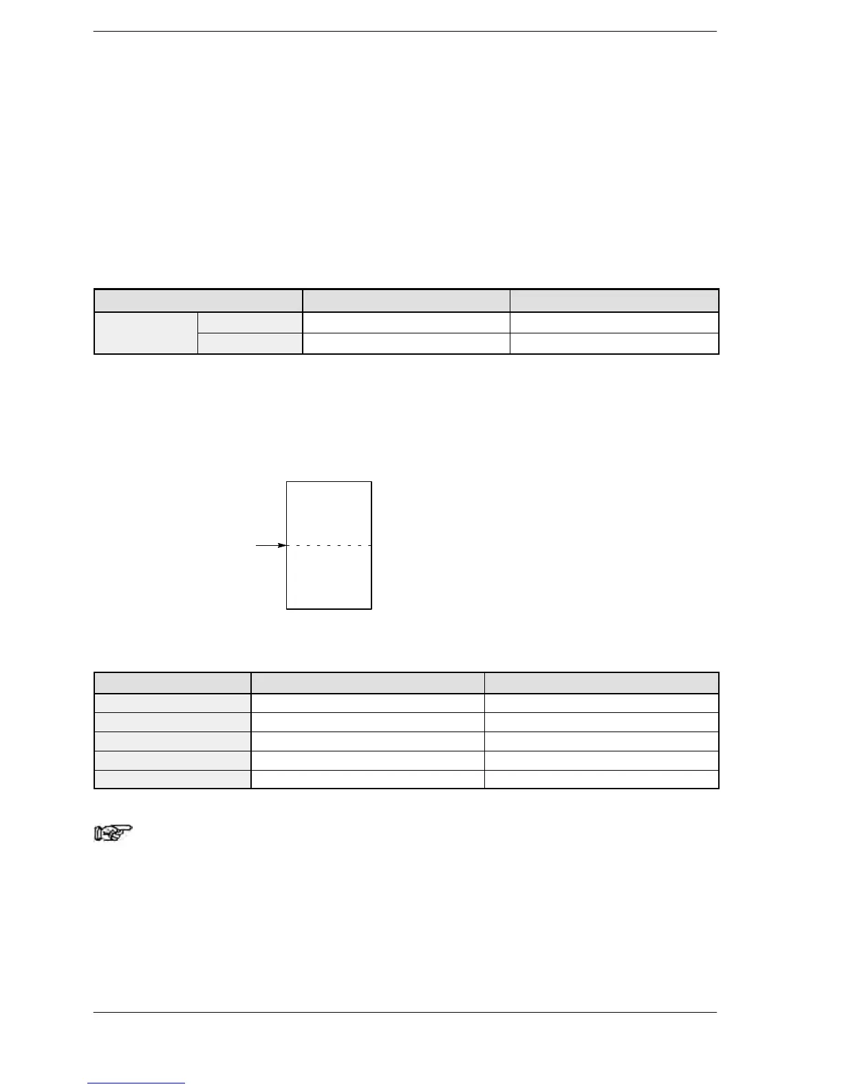
For theFP0 T32C/FPΣ/FP0R/FP−X/FP2/FP2SH/FP10SH, and FP−e with
clock/calendar function, system register 8 can be used to specify whether hold types
or non−hold types are to be used. If the beginning of a hold type data register is
specified using a word number, data registers before that point will be non−hold
types, and subsequent data registers will be hold types.
Value of system register 8
(initial number of hold type)
Non-hold
type
Hold type
Default settings for hold types and non−hold types
Type Non−hold type Hold type
FPΣ,FP−X (C30, C60) DT0 to DT32709 (32710 words) DT32710 to DT32765 (55 words)
FP−X (C14) DT0 to DT12229 (12230 words) DT12230 to DT12284 (55 words)
FP−e DT0 to DT1651 (1652 words) DT1652 to DT1659 (8 words)
FP0R C10, C14, C16 DT0 to DT11999 (12315 words) DT12000 to DT12314 (315 words)
FP0R C32, T32, F32 DT0 to DT32449 (32451 words) DT32450 to DT32764 (315 words)
Note
For FPΣ,FP−X and FP−e, in case of not using back−up battery,
please keep the default value. Otherwise we cannot guarantee
the function of hold/non−hold value.
For the FP2/FP2SH/FP10SH, if the Initialize/Test switch is set to the upper side (the
Initialize side) in the PROG mode, all data registers (DT) are cleared to 0. Even if a hold
type has been specified, these are cleared to 0.