Relays, Memory Areas and Constants
1-46
Note
With the FP2SH/FP10SH, system register 4 can be set in such a
way that the data registers are not cleared even if the Initialize/
Test switch is set to the upper side.
1.3.2 Special Data Registers (DT)
Function of the special data registers
These data registers have specific applications.
Data cannot be written to most of them using instructions such as F0 (MV).
With the FP0 T32C, FP0R, FPΣ,FP−X, FP2, FP2SH, FP10SH and the FP0 C10/C14/C16/
C32, FP−e, the special data registers have dif ferent numbers, but the last three digits of
the numbers are the same.
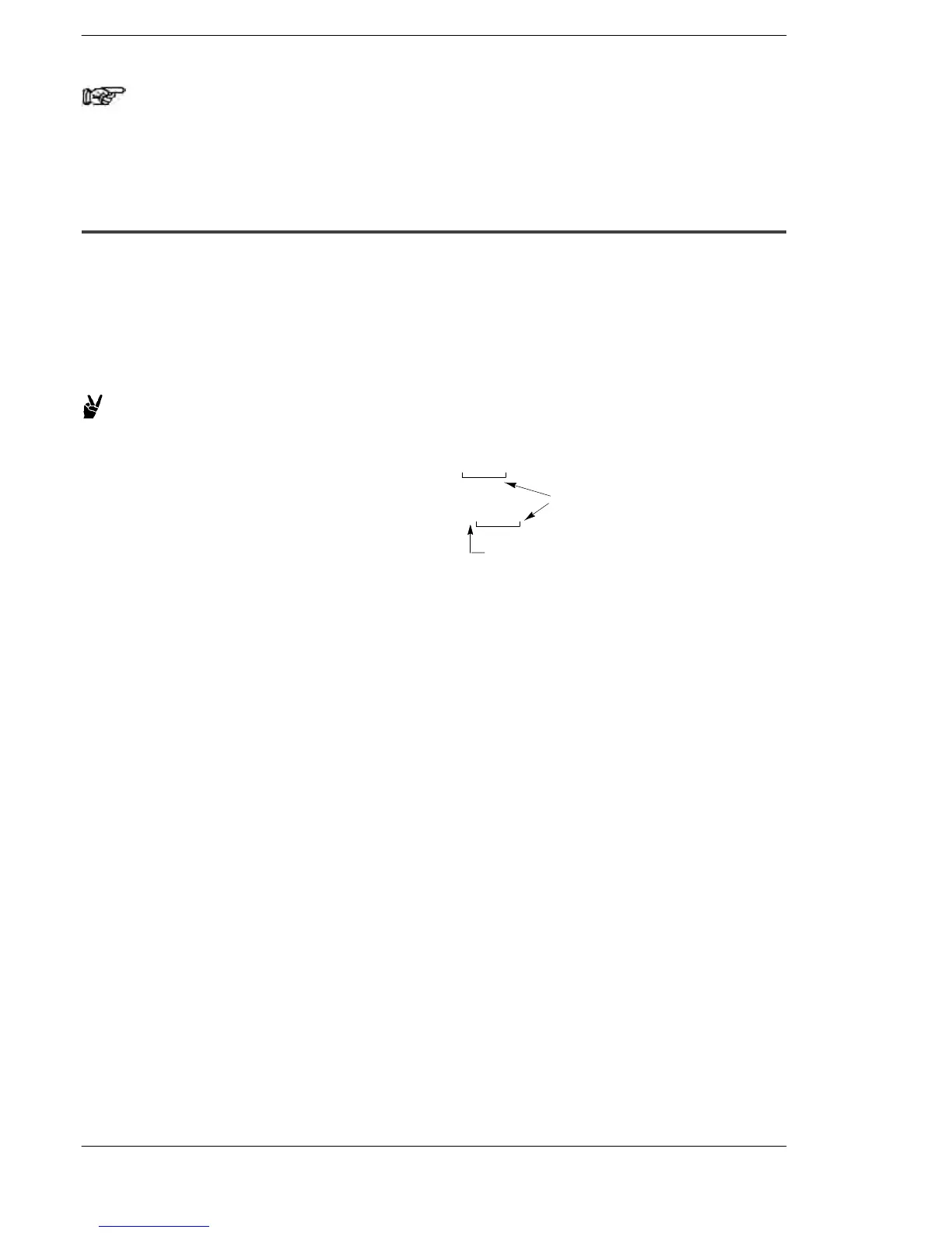
Example:
If a “0” is added, this becomes
the five−digit number used with
the FP0 T32C, FPΣ,FP−X, FP0R,
FP2, FP2SH and FP10SH.
The last three digits
are the same.
DT9055
With the FP0 T32C, FP0R
FPΣ,FP−X, FP2, FP2SH and
FP10SH:
DT90055
With the FP0 C10/C14/
C16/C32, FP−e:
The main functions of special data registers are:
Environmental settings and operation statuses
The operation statuses of the programmable controller specified with the system
registers and the various types of instructions are stored.
− Link communication status (DT9140 to DT9254/DT90140 to DT90254)
− High−speed counter control flag (DT9052/DT90052) and others
Error contents
The unit in which the error occurred, and other information, is stored.
− Self−diagnostic error code (DT9000/DT90000)
− The slot number of the unit where the error occurred (DT9002, DT9003, etc.)
− Remote input/output error slave station numbers (DT9131 to DT9135)
− The address where the operation error occurred (DT9017, DT9018/DT90017,
DT90018)