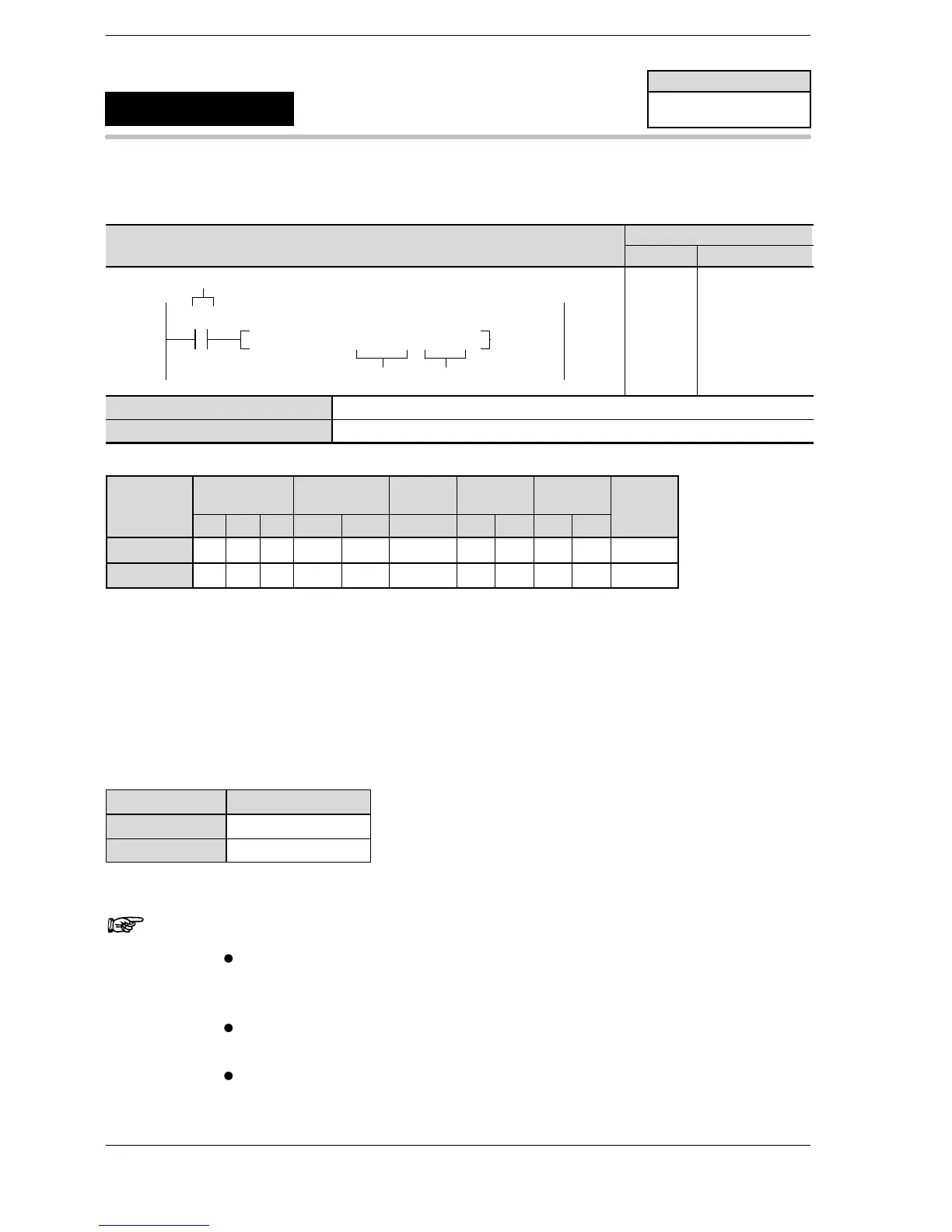
WX WY WR SV EV DT IX IY K H
modifier
S N/A N/A N/A N/A N/A A N/A N/A N/A N/A A
n N/A N/A N/A N/A N/A N/A N/A N/A A A N/A
Description
When the corresponding control flag is off and execution condition (trigger) is in the on state, a PWM is output
from the specified channel. The PWM is output while the execution condition (trigger) is in the on state.
The frequency and duty are specified with the data table on the right made by a user program.
Since the output is delayed near the maximum and minimum levels, the set duty ratio will differ.
The duty can be changed each scan. The frequency settings is only effective at the start of the execution of
the instruction (becomes effective after the next pulse output).
See below for the corresponding areas.
Channel no. Control flag
ch0 R903A
ch1 R903B
Notes
When this instruction is used, the setting for the channel
corresponding to system register 400 should be set to
“High−speed counter not used”.
By performing a rewrite during RUN while operating, the pulse
output will stop during rewriting.
If both the regular program and the interrupt program contain
code for the same channel, make sure both are not executed
simultaneously.
FP0/FP−e
PWM output
(with channel specification)
5
F170
(PWM)
Availability
FP0/FP−e
A: Available
N/A: Not Available












 To Next Page