WX WY WR SV EV DT I K H
modifier
S N/A N/A N/A N/A N/A A N/A N/A N/A A
n N/A N/A N/A N/A N/A N/A N/A A A N/A
Description
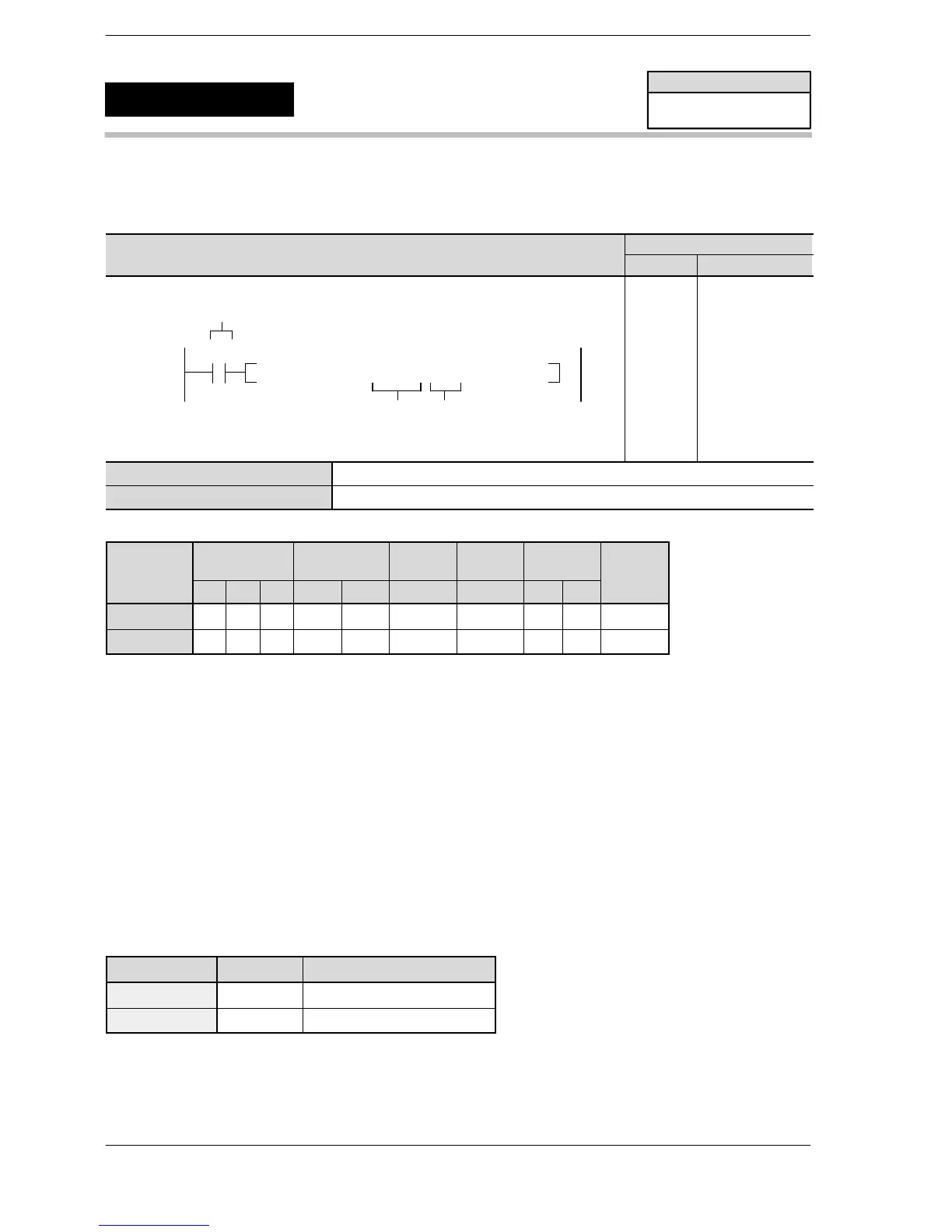
When the corresponding control flag is off and the execution condition is in the on state, a PWM is output from
the specified channel for the PWM output. The PWM is output while the execution condition is on.
The data table shown at below, indicating the frequency and duty, is created and the values are specified by
the user program.
The duty, particularly when it is close to the minimum or maximum value, may be off from the specified ratio,
depending on the load voltage and load current.
The duty can be changed for each separate scan. Control codes, however, cannot be changed while an
instruction is being executed.
Table of areas used
For FP Σ
Channel no. Output Control flag
ch0 Y0 R903A
ch2 Y3 R903C
FPΣ/FP−X
PWM output
(with channel specification)
F173
(PWMH)
Availability
FPΣ/FP−X/FP0R
A: Available
N/A: Not Available












 To Next Page