Boolean
Ladder Diagram
Address Instruction
10
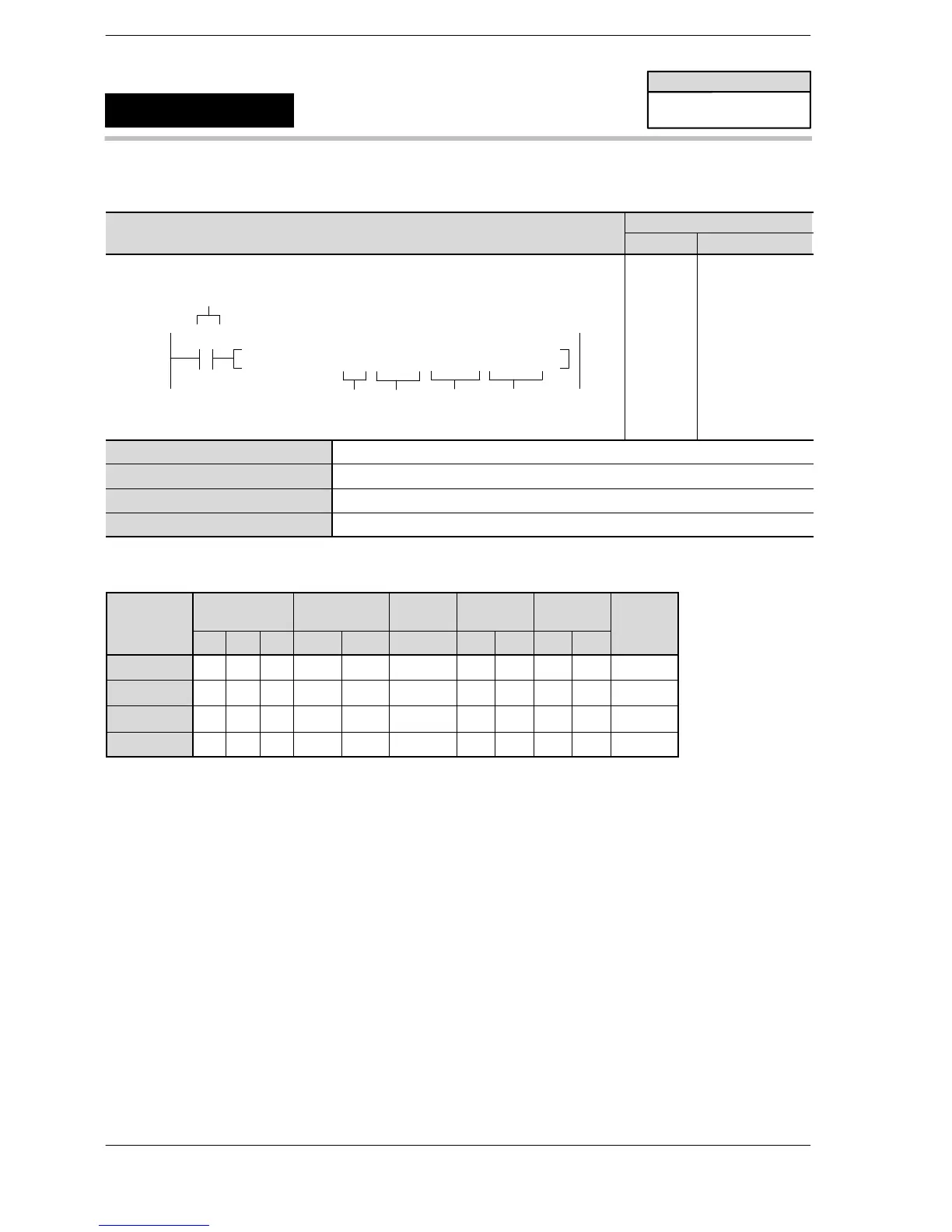
F180 SCR, H0, DT 10, DT100, DT 101
S1
Trigger
R0
S3
S2
S4
10
11
ST R 0
F180 (SCR)
H0
DT 10
DT 100
DT 101
S1 FP−e screen mode and number (Specify between 0 and 3.)
S2 Starting address of area specified for the FP−e display method
S3 Area for storing data to be displayed in the upper of the FP−e
S4 Area for storing data to be displayed in the lower of the FP−e
Note: A special data register cannot be specified for S4.
Operands
O
WX WY WR SV EV DT IX IY K H
modifier
S1 A A A A A A A A A A A
S2 A A A A A A N/A N/A N/A N/A A
S3 A A A A A A A A N/A N/A A
S4 N/A A A A A A A A N/A N/A A
Description
Register FP−e screens specified with S1 with the method whereby S2 to S2+2 is specified.
For S3, specify the address where data for display in the upper is stored. For S4, specify the address where
data for display in the lower is stored.
When this instruction is executed, the registered screen is displayed in the FP−e panel.
To switch screens, use the mode switch on the FP−e, or instruction F180 or F181.
Specify the screens for setting with S1.
Specify the display method with S2, S2+1 and S2+2.
Specify the data to be displayed in the upper with S3.
Specify the data to be displayed in the lower with S4.
Note) For the numeric data display of S3 and S4, only 16−bit data is available.
Precautions during programming
This instruction cannot be used during the interrupt program.
FP–e
FP−e screen display registration
F180
(SCR)
Availability
FP−e
A: Available
N/A: Not Available












 To Next Page