WX WY WR SV EV DT IX IY K H
modifier
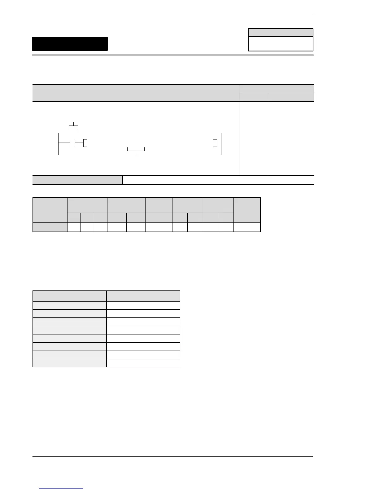
S A A N/A A A A A A A A A
Description
Switches the FP−e screen to the screen of the mode specified with S.
How to specify S
Specify the type of FP−e mode.
Value specified for S Type of mode
K0 N mode first screen
K1 N mode second screen
K2 S mode first screen
K3 S mode second screen
K4 R mode first screen
K5 R mode second screen
K6 I mode first screen
K7 I mode second screen
Precautions during programming
If specifying the value other than 0 to 7 for S, an operation error will occur.
This instruction cannot be used during the interrupt program.
Flag conditions
・Error flag (R9007): Turns on and stays on when:
・Error flag (R9008): Turns on for an instant when:
− The area specified using the index modifier exceeds the limit.
− The value of S is number except 0 to 7.
FP–e
FP−e screen display switching
F181
(DSP)
Availability
FP−e
A: Available
N/A: Not Available












 To Next Page