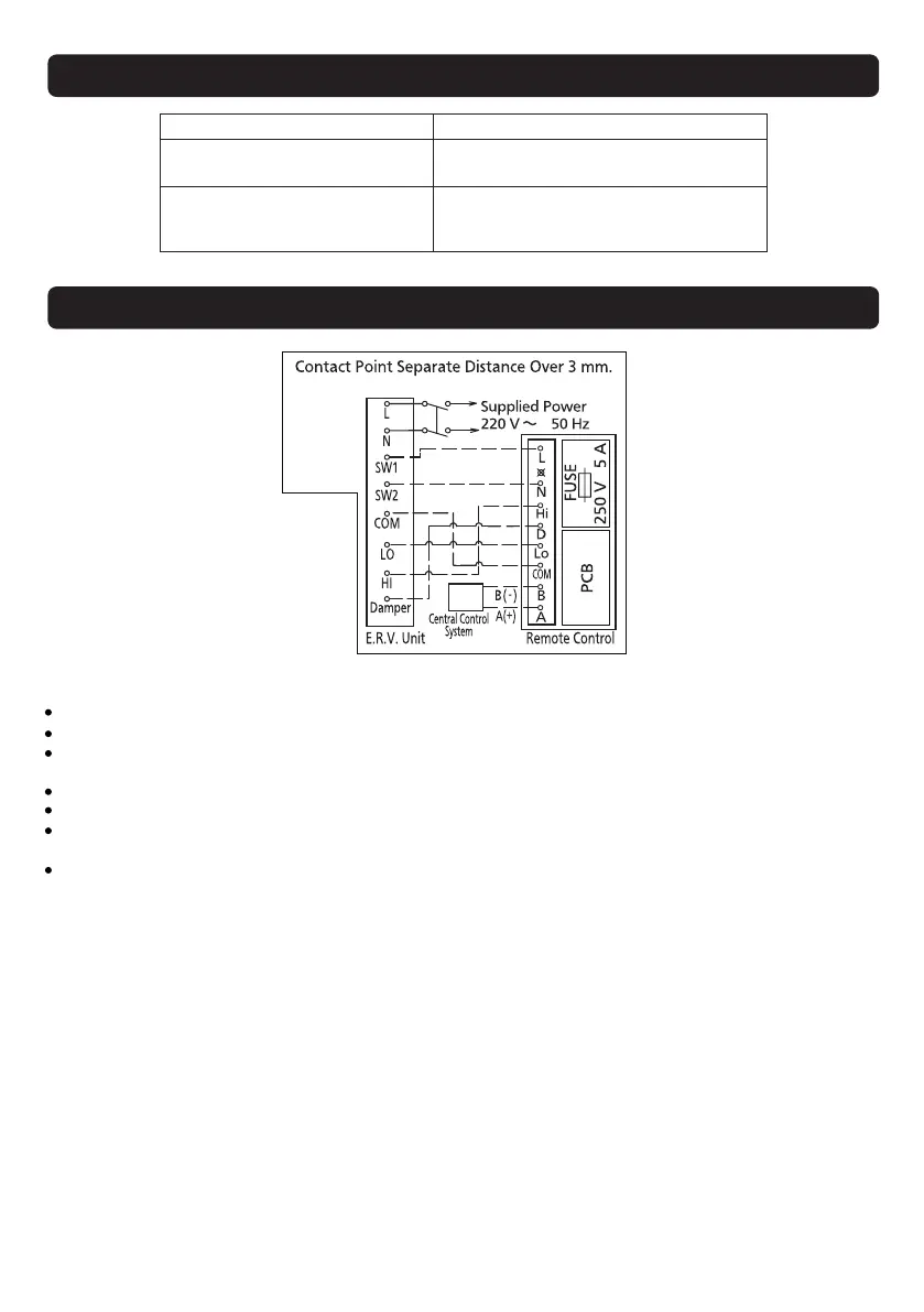
The dotted lines in the diagram indicate wiring to be carried out on site by qualified professionals.
Be sure to isolate the power supply before wiring.
It’s recommended to use the cable for connecting power main unit and switch, with a rated voltage of
300 V/500 V as stipulated in 60227 IEC 10 (fixed wiring). Cross-section area for each core wire is 1.5 mm
2
.
No more than 10 units can be connected, as over-current may result in fire.
Protective gloves should be worn during installation.
After the connection is complete, be sure to close the back cover of the remote control and confirm that it is
clamped tightly.
Please read the Installation and Operating Instructions carefully before wiring.
Notes:
Solution
Phenomenon
The product does not work after
the standby switch is turned on.
Is the power supply connected?
Is there a power failure?
The ERV does not act after
the remote control is operated.
Is the power cord connection loose?
Is the connection to the ERV correct?
Is the wire connected to the ERV loose?
TROUBLESHOOTING
WIRING DIAGRAM
13