7
2-4. Fix the base into the switch box
Refer to “1-3. Fix the base into the switch box” in the section “How to Install”.
2-5. Fix the top cover
Refer to “1-4. Fix the Top Cover” in the section “How to Install”.
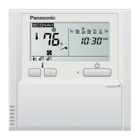
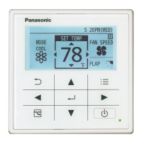
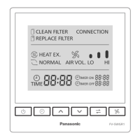
When installation is complete, turn on the power, press each of the function keys on the remote control
to check if the ERV works correctly. If the ERV does not operate, please check if the power supply is
terminated correctly and securely.
Specifications
Start-stop synchronous mode; start bit: 1bit; data bit: 8bit; stop bit: 1bit;
parity check bit: nil
Information transfer mode
Check Field
Address bar
Basic form of protocol
Data zone
Valid scope of the address: 1-63
Adopt the 16-bit CRC (Cyclic Redundancy Check) in the MODBUS-RTU mode.
Modbus frame structure
Byte order used in the Modbus data zone: Big-Endian.
(High-order byte → Low-order byte)
9600 bps
Data transfer rate
HOW TO INSTALL(RS485 CONNECTION)
TEST RUN
RS485 CONNECTION SETTINGS