EasyManua.ls Logo

Panasonic FX-501 Series User Manual

Panasonic FX-501 Series
13 pages
To Next Page IconTo Next Page
Page #1 background imageLoading...
Page #1 background image
1
InstructIons
Digital Fiber Sensor Amplier
FX-501□, FX-502□, FX-505□-C2 Series
Thank you for purchasing products from Panasonic Electric Works SUNX
Co., Ltd. Please read this Instruction Manual carefully and thoroughly for
the correct and optimum use of this product. Kindly keep this manual in a
convenient place for quick reference.
WARNING
Never use this product as a sensing device for personnel protection.
In case of using sensing devices for personnel protection, use prod‑
ucts which meet laws and standards, such as OSHA, ANSI or IEC
etc., for personnel protection applicable in each region or country.
1
Compliance with standards
This product complies with the following standards and
regulations.
For the EU: EMC Directive 2004/108/EC
For the US and Canada:
ANSI/UL60947‑5‑2, CAN/CSA C22.2 No.14
For Korea: S1‑G‑1‑2009, S2‑W‑5‑2009
* In case you require a UL listing mark or C-UL
listing mark, use a class 2 power supply unit.
2
Part description
FX-501
1 2 3 4
56789
1
Operation indicator for sensing output (orange)
2
Digital display (green/red)
3
UP key (+) Functions:
Teach
Fine adjustment of the threshold value
Select settings
4
DOWN key (–)
5
MODE key Functions:
Select modes
Cancel
6
SET key Functions:
Teach
Save selected settings
7
Mode indicator PRO mode (yellow), see page 6
8
Mode indicator CUST (custom) mode (yellow), see page 5
9
Mode indicator L /D (Light‑ON/Dark‑ON) mode (yellow)
FX-502□ and FX-505□-C2
1 2 3 4 5
67890
1,
Sensing output 1 (lit if output is active)
Orange: Sensing output is operating
2
Sensing output 2 (lit if output is active)
Orange: Sensing output is operating
3
Digital display (green/red)
4
UP key (+) Functions:
Teach
Fine adjustment of the threshold value
Select settings
5
DOWN key (–)
6
MODE key Functions:
Select modes
Cancel
7
SET key Functions:
Teach
Save selected settings
8
Mode indicator PRO mode (yellow)
9
Mode indicator CUST (custom) mode (yellow)
0
Mode indicator L /D (Light‑ON/Dark‑ON) mode (yellow)
* To toggle the key lock function ON/OFF, press the SET and the
MODE key together for 3 seconds.
3
Mounting
Installation to a DIN rail
1. Attach the railing on the rear of the ampli
er to the DIN rail.
2. Push the amplier in the direction of the
arrow as illustrated so that it attaches
securely.
1.
2.
Removal from a DIN rail
1. Push the amplier forward.
2. Lift the front part of the amplier up.
1.
2.
Connecting the ber cable
* The attachments to the ber cables need to be tted BEFORE
you insert the bers into the amplier. For details, refer to the
instruction manual enclosed with the bers.
1. Snap the ber lock lever 1 down as
far as it will go.
2. Insert the ber cables slowly into the
inlets until they stop (see note).
3. Return the ber lock lever to the
original position.
2.
1.
3.
1
2
3
* With the coaxial reective type ber, such as FD-G4 or FD-FM2,
insert the single core ber cable into the inlet for the emitter 2
(inlet on the amplier is labeled “P”) and the multi-core ber
cable into the inlet for the receiver 3. If they are inserted the
wrong way round, the sensing performance will deteriorate.

Other manuals for Panasonic FX-501 Series

Question and Answer IconNeed help?

Do you have a question about the Panasonic FX-501 Series and is the answer not in the manual?

Panasonic FX-501 Series Specifications

General IconGeneral
BrandPanasonic
ModelFX-501 Series
CategoryAmplifier
LanguageEnglish

Summary

Introduction and Safety Precautions

General Warnings

Provides critical safety warnings regarding personnel protection and proper usage.

Compliance with Standards

Lists the international standards and regulations this product complies with.

Part Description and Controls

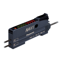
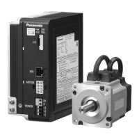
Details the physical components, indicators, and button functions of the amplifier.

Mounting and Cable Connection

Instructions for installing the amplifier on a DIN rail and connecting fiber cables.

Amplifier Cascading and Wiring

Cascading Amplifiers

Procedure for connecting multiple amplifiers together using optional cables.

I/O Circuit Diagrams

Illustrates the input/output circuits for various amplifier models.

Operation and Teaching Procedures

Mode Selection

Explains how to switch between RUN, CUSTOM, and PRO modes.

Teaching Method Overview

Introduces different teaching methods and their recommended applications.

2-Point Teaching

Detailed steps for the primary 2-point teaching method.

Limit Teaching

Instructions for limit teaching, suitable for small objects or background interference.

Full Auto Teaching

Procedure for auto teaching, ideal for moving objects.

Advanced Teaching Methods

1-Point Teaching

Method for setting threshold range using a shift amount.

Window/Hysteresis Teaching

Teaching methods for window comparator and hysteresis modes.

Fine Adjustment and Key Functions

Threshold Value Fine Adjustment

Guides on adjusting threshold values after initial teaching.

Key Lock Function

How to activate and deactivate the key lock to prevent accidental changes.

Sensing Output Mode (L/D)

Procedure for switching between Light-ON and Dark-ON modes.

Custom Mode (CUST)

Explanation of how to use and set up the custom mode for quick access.

Advanced Configuration (PRO Mode)

Navigating PRO Mode

Explains how to access and navigate through the PRO mode menus.

PRO1 Menu Details

Details on response time, timer, hysteresis, and shift amount settings.

PRO2 Menu Details

Details on teaching lock, digital display, and emission power settings.

PRO3 Menu Details

Details on timer range, data bank, and backup settings.

PRO Mode Menu Details (Continued)

PRO4 Menu Details

Details on copy settings, communication protocol, and external input.

PRO5 Menu Details

Details on code setting, display adjustment, and interference prevention.

PRO6 Menu Details

Details on sensing output modes, including normal, comparator, and differential.

PRO7 Menu Details

Details on logic operation, threshold follow-up, and algorithm settings.

Menu Item Descriptions

PRO1-PRO3 Menu Item Explanations

Detailed explanations for settings within PRO1, PRO2, and PRO3 menus.

Menu Item Descriptions (Continued)

PRO4-PRO5 Menu Item Explanations

Detailed explanations for settings within PRO4 and PRO5 menus.

PRO6 Menu Item Explanations

Detailed explanations for settings within PRO6 menu.

Code Setting Tables

Green Digital Display Codes

Code tables for setting the green digital display for various functions.

Red Digital Display Codes

Code tables for setting the red digital display for various functions.

Optical Communication

Optical Communication Functions

Overview of functions enabled by optical communication, including copy and data bank.

Mounting for Communication

Guidelines for mounting amplifiers to ensure proper optical communication.

FX-5050-C2 Communication Codes

Specific digital display code tables for the FX-5050-C2 model.

Notes on Optical Communication

Conditions under which optical communication is not possible.

Interference Prevention and Troubleshooting

Interference Prevention

Methods to prevent interference between amplifiers using optical communication or frequency.

Error Codes and Troubleshooting

Lists common error codes and their corresponding remedies.

General Cautions

Important cautions regarding product usage, environment, and electrical safety.

Specifications

Model and Power Specifications

Details on model numbers, supply voltage, and power consumption.

Output and Response Specifications

Technical specifications for output types, response times, and input signals.

Environmental and Cable Specifications

Information on protection ratings, operating environment, materials, and cables.

Related product manuals