Do you have a question about the Panasonic HC-X920P and is the answer not in the manual?
Important safety notices and general guidelines for servicing equipment.
Procedures for cold and hot leakage current checks.
Procedure to safely discharge the capacitor on the Flash P.C.B. before servicing.
Guidelines to prevent damage to sensitive electronic components from static electricity.
Information on recycling lithium-ion batteries (U.S. only).
Precautions for the AC cord, including fuse replacement and wiring.
Step-by-step instructions for replacing the internal lithium battery.
Overview of the manual and details on lead-free solder.
Important notices regarding serviceability and recycle module parts.
Method to identify the specific model suffix based on safety marks.
Procedure for formatting SD cards and built-in memory.
Procedure for baking ICs and PCBs to prevent damage during replacement.
Details on power, recording formats, and media for NTSC models.
Continues NTSC specs: image stabilizer, monitor, viewfinder, and connectors.
Approximate recordable times for different modes and media.
Approximate number of recordable pictures for various resolutions and media.
Compatible SD cards and charging/recording times.
Details on power, recording formats, and media for PAL models.
Continues PAL specs: image stabilizer, monitor, viewfinder, and connectors.
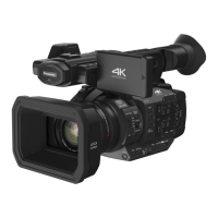
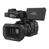
Identifies primary buttons, levers, and indicators on the camera body.
Locates the lens, SD card slot, battery access, and input/output ports.
Details the viewfinder, touch screen operations, and mode selection.
Instructions on accessing and navigating the service mode.
Covers factory reset, self-checks, error history, and calibration procedures.
Details service adjustments, data backup, restore, and specific settings.
Notes on post-replacement adjustments and service positions.
Lists and describes specific extension cables used for servicing.
Visual chart outlining the disassembly sequence for the entire unit.
Diagrams showing the physical locations of various PCBs within the unit.
Comprehensive step-by-step instructions for disassembling the unit.
Specific steps for removing the left side case unit.
Steps for removing the SD OP PCB and cover board unit.
Procedure for removing the ESD PCB, specific to HC-X920M.
Steps for removing the top case unit.
Procedure for removing the front case unit.
Detailed steps for removing the lens unit and associated parts.
Procedure for removing these specific PCBs and FPCs.
Steps for removing the heat radiation sheet and the main PCB.
Procedures for removing the cooling fan motor and LCD panel unit.
Steps for removing the LCD frame and monitor PCB.
Steps for removing the front PCB.
Procedure for removing the barrier motor unit.
Steps for removing the flash and barrier case unit.
Procedure for removing manual focus parts and related FPC.
Steps for removing the EVF unit and top frame.
Procedures for removing the Wi-Fi PCB and operation/DC jack units.
Steps for removing the microphone amplifier PCB and camera function FPC.
Procedures for removing microphone, prism, filter, and stepping motor.
Procedure for removing the EVF slide case and extension PCB.
Steps for removing the LCD and EVF lens components.
Overview of electric adjustment procedures and necessary jigs.
Steps for connecting the unit and entering service mode for adjustment.
Lists and describes optical jigs required for camera adjustment.
Lists all adjustable components and required adjustments.
Detailed steps for accessing and performing service adjustments.
Procedure to set the filename for saving adjustment data.
Procedure to select and set the correct model for adjustments.
Steps to execute the backup of adjustment data to an SD card.
Procedure to verify the functionality of all camera switches.
Performing camera-specific adjustments like Iris, Gyro, and OIS.
Procedures for zoom/tracking and indoor white balance adjustment.
Procedures for outdoor white balance and level shot adjustment.
Detailed steps and conditions for level shot adjustment.
Procedure to activate factory settings and reset the unit.
Explains what settings are cleaned up or refreshed by factory settings.
High-level block diagram showing main functional units and their connections.
Detailed block diagram of the system control circuits.
Block diagram illustrating video/audio signal processing path 1.
Block diagram illustrating video/audio signal processing path 2.
Block diagram showing the camera's internal circuitry.
Block diagram illustrating the lens drive system.
Block diagram of the camera's power supply system.
Diagram showing how internal components and PCBs are interconnected.