EasyManua.ls Logo

Panasonic JU-475-4 - User Manual

Panasonic JU-475-4
33 pages
Print Icon
To Next Page IconTo Next Page
Loading...
ORDER NO. MSD891122000
erviceManual
Flexible Disk Storage Drive
JU-475-4
Panasonic

Table of Contents

Questions and Answers

  • C
    Cynthia PetersonJul 30, 2025
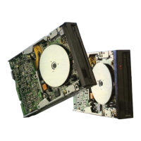
    Why does my Panasonic JU-475-4 have a read error?
    • G
      grahamwendyJul 30, 2025
      A read error in your Panasonic Storage device could be due to various factors. Possible solutions include checking the alignment, azimuth, index burst, asymmetry, limiter, Track 0, head load time, or index period. Additionally, the PCB read circuit might be faulty.
  • J
    Joshua HayesAug 4, 2025
    What to do if my Panasonic JU-475-4 Storage is not writing?
    • W
      William BookerAug 4, 2025
      If your Panasonic Storage device is not writing, the issue could stem from several sources. Check the head connection for disconnections or shorts. Also, verify the head load bail height. A faulty PCB write circuit could also be the cause.
  • D
    Douglas LozanoAug 8, 2025
    What causes a Panasonic JU-475-4 Storage index detection failure?
    • C
      Clifford AndersonAug 8, 2025
      An index detection failure in your Panasonic Storage could be due to a faulty collet part, drive motor control PCB, drive motor, index LED, or index detector. The index LED/detector installation might be faulty. Alternatively, the PCB motor on the circuit or the PCB index detection circuit could be the problem.
  • R
    rachelroblesAug 12, 2025
    Why won't the IN USE LED light up on my Panasonic JU-475-4?
    • D
      Dennis DodsonAug 12, 2025
      If the IN USE LED on your Panasonic Storage device isn't lighting up, it could be due to a faulty LED part or an issue with the PCB IN USE circuit.
  • P
    Patrick JonesAug 17, 2025
    What causes a Panasonic JU-475-4 Storage to not seek?
    • L
      lisa76Aug 17, 2025
      If your Panasonic Storage device is not seeking, the issue might be a faulty stepper motor, contamination or damage to the guide shaft, or a problem with the PCB stepper driver circuit.
  • L
    lynnjuliaAug 20, 2025
    Why does my Panasonic JU-475-4 show a write protect failure?
    • L
      ldiazAug 20, 2025
      A write protect failure in your Panasonic Storage device could be caused by a faulty write protect part or a problem within the write protect circuit.
  • S
    samueladkinsAug 26, 2025
    What causes Panasonic Storage to have no head loading?
    • T
      Teresa WilcoxAug 26, 2025
      If your Panasonic Storage device is experiencing no head loading, consider checking the head load solenoid or the PCB head load circuit.

Summary

Introduction to Service Manual

5.25-inch FDD Model Identification

5.25-inch FDD Series Models

Details on identifying different 5.25-inch Floppy Disk Drive models.

Special Tools for FDD Maintenance

Outline of Maintenance Procedures

Alignment Diskette Usage

How to use the alignment diskette for head actuator alignment and index sensor adjustment.

FDD Exerciser Functions

Description of the exerciser's capabilities for adjustments and inspections.

Diagnostic Procedures for FDD Troubleshooting

Error Symptom Recognition

How to identify and recognize symptoms of floppy disk drive errors.

Soft Error Detection and Correction

Methods for detecting and correcting soft errors in FDDs.

Write Error Troubleshooting

Procedures for identifying and resolving write errors during FDD operation.

Read Error Troubleshooting

Procedures for identifying and resolving read errors during FDD operation.

Seek Error Troubleshooting

Procedures for identifying and resolving seek errors in FDD head movement.

Interchangeability Error Troubleshooting

Procedures for diagnosing and resolving data interchangeability errors between FDDs.

Trouble Analysis for FDD Issues

Trouble Analysis Procedure

Step-by-step procedure for analyzing floppy disk drive troubles.

Troubleshooting Flow Chart

Visual flowchart to guide troubleshooting of FDD problems.

Trouble Analysis Table

A table correlating troubles with their causes and solutions.

Preventive Maintenance for FDD

FDD Technical Specifications

Adjustments and Verifications

Motor Speed Verification (Index Period)

How to verify motor speed using the index period.

Write Protect Verification

Verifying the functionality of the write protect sensor.

Head Output Verification

Verifying the output signal level from the read/write heads.

Output Modulation Verification

Verifying the modulation of the read/write head output signal.

Resolution Verification

Verifying the read/write head resolution.

Radial Alignment Verification and Adjustment

Procedures for verifying and adjusting head radial alignment.

Azimuth Verification

Verifying the azimuth angle of the read/write heads.

Index Burst Verification and Adjustment

Verifying and adjusting the index burst timing.

Track 0 Sensor Adjustment

Adjusting the track 0 sensor for accurate head positioning.

Asymmetry Verification

Verifying the asymmetry of read/write signals.

Printed Circuit Board Test Points

Panasonic Alignment Diskette Details

Removals and Installations Procedures

PCB Removal and Installation

Step-by-step instructions for removing and installing the PCB.

Front Plate and Handle Removal and Installation

Instructions for removing and installing the front plate and handle.

Track 0 Sensor Removal and Installation

Procedures for removing and installing the track 0 sensor assembly.

Collet Assembly Removal, Installation, and Adjustment

Steps for removing, installing, and adjusting the collet assembly.

Clamp Assembly Removal and Installation

Instructions for removing and installing the clamp assembly.

Write Protect Sensor Assembly and Index Sensor Assembly Removal and Installation

Procedures for removing and installing write protect and index sensors.

Cartridge Guide Assembly Removal and Installation

Steps for removing and installing the cartridge guide assembly.

Stepper Motor Assembly Removal and Installation

Procedures for removing and installing the stepper motor assembly.

Head Carriage Assembly Removal and Installation

Steps for removing and installing the head carriage assembly.

Drive Motor Removal and Installation

Procedures for removing and installing the drive motor.

LED Assembly Removal and Installation

Steps for removing and installing the LED assembly.

Lifter Unit Removal and Installation

Procedures for removing and installing the lifter unit.

Media Lifter Removal and Installation

Steps for removing and installing the media lifter.

Media Sensor Assembly Removal and Installation

Procedures for removing and installing the media sensor assembly.

Exploded View of JU-475-4 AGG

Replacement Parts List

Replacement Parts List for PCB (1)

Schematic Diagram of JU-475-4 AGG

Circuit Board Layout

Block Diagram of JU-475-4

Panasonic JU-475-4 Specifications

General IconGeneral
BrandPanasonic
ModelJU-475-4
CategoryStorage
LanguageEnglish

Related product manuals