13
5 Service Fixture & Tools
5.1. When Replacing the Main PCB
After replacing the MAIN PCB, be sure to achieve adjustment.
The adjustment instruction is available at “software download” on the “Support Information from NWBG/VDBG-PAVC” web-site in
“TSN system”, together with Maintenance software.
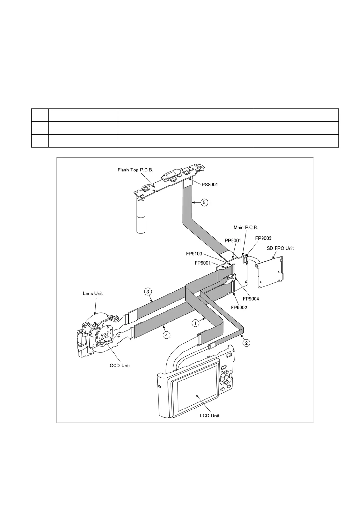
5.2. Service Position
This Service Position is used for checking and replacing parts. Use the following Extension cables for servicing.
Table S1 Extension Cable List
CAUTION-1. (When servicing FLASH TOP PCB)
1. Be sure to discharge the capacitor on FLASH TOP PCB.
Refer to “HOW TO DISCHARGE THE CAPACITOR ON FLASH TOP PCB”.
The capacitor voltage is not lowered soon even if the AC Cord is unplugged or the battery is removed.
2. Be careful of the high voltage circuit on FLASH TOP PCB.
3. DO NOT allow other parts to touch the high voltage circuit on FLASH TOP PCB.
No. Parts No. Connection Form
1 RFKZ0354 FP9103 (MAIN) - LCD UNIT 37PIN 0.3 FFC
2 VFK1974 FP9004 (MAIN) - LCD UNIT 4PIN 0.5 FFC
3 RFKZ0416 FP9001 (MAIN) - CCD UNIT 41PIN 0.3 FFC
4 RFKZ0477 FP9002 (MAIN) - LENS UNIT 45PIN 0.3 FFC
5 RFKZ0418 PP9001 (MAIN) - PS8001 (FLASH TOP) 30PIN B to B
 Loading...