Do you have a question about the Panasonic Lumix DMC-FS5P and is the answer not in the manual?
Important safety notice regarding critical components and servicing procedures.
Procedure to check leakage current with the AC cord unplugged using an ohmmeter.
Procedure to check leakage current with power applied using a voltmeter.
Procedure to safely discharge high-voltage capacitors on the Flash Top PCB.
Techniques to reduce component damage caused by static electricity during handling.
Information on recycling lithium-ion batteries for the product.
Safety information, fuse replacement, and wiring for the AC cord.
Procedure for safely replacing the lithium battery in the device.
Overview of the service manual's purpose and how to use it for servicing.
Explanation of lead-free solder, its distinction, and precautions for use.
Method to identify model suffixes (NTSC/PAL) by checking nameplate markings.
Procedure for performing initial settings and configuration after replacing the Main PCB.
Table listing default settings for various model suffixes after initial setup.
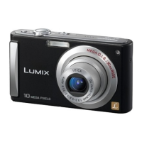
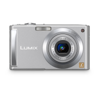
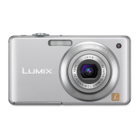
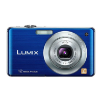
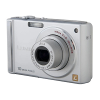
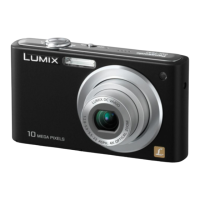
Details on camera features, sensor, lens, zoom, focus, and shutter.
Details on motion picture recording, burst recording, and media.
Specifications for image quality, file formats, interfaces, power, and battery.
Dimensions, weight, operating temperature, and humidity.
Notes on adjustment procedures after replacing the Main PCB.
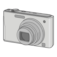
Description of service positions and required extension cables for servicing.
Instructions for cleaning the camera's lens and LCD panel.
Safety notices regarding schematic diagrams and component identification.
Table of standard voltage values for the Main PCB.
Block diagram showing the system control circuits and their connections.
Block diagram illustrating the video and audio processing circuits.
Block diagram detailing the image sensor and its related circuitry.
Block diagram showing the lens drive mechanisms and control circuits.
Block diagram illustrating the power supply and management circuits.
Detailed schematic for the power supply section of the main PCB.
Schematic diagram for the external connection jacks (USB, AV).
Schematic diagram for the image sensor and its associated circuitry.
Schematic diagram for the LCD display and its driver circuits.
Schematic diagram for the digital processing and control circuits.
Schematic diagram for the gyro sensor and zoom encoder circuits.
Schematic diagram illustrating the system driver circuits and connections.
Schematic diagram for the rear panel buttons and power LED.
Schematic showing the main connections between different sections of the PCB.
Component layout diagrams for the Main PCB (Component Side and Foil Side).
Table mapping integrated circuits and components to their PCB locations.
Reference to ESD precautions section for handling sensitive components.
Information on how parts are supplied and marked by different vendors.
List of replacement parts for various DMC-FS5 models, categorized by component type.
| Camera Type | Compact |
|---|---|
| Sensor Type | CCD |
| Optical Zoom | 4x |
| Digital Zoom | 4x |
| LCD Screen Resolution | 230, 000 dots |
| Image Stabilization | Optical |
| Shutter Speed | 8 - 1/2000 sec |
| Image sensor size | 1/2.33 inch |
| Screen Size | 2.5" |
| LCD Screen Size | 2.5" |
| ISO Sensitivity | Auto, 100, 200, 400, 800, 1600 |
| Supported Flash Memory | SD, SDHC |
| Storage Media | SD, SDHC |
| Battery Type | Lithium-Ion rechargeable battery |