Do you have a question about the Panasonic LUMIX DMC-GX7P and is the answer not in the manual?
Essential safety notices for servicing equipment and preventing hazards.
Procedure to measure resistance between AC plug and exposed parts to check for shock hazards.
Procedure to measure voltage across a test circuit for exposed parts to detect shock hazards.
Steps to safely discharge high-voltage capacitors on the flash circuit board before servicing.
Techniques to prevent damage to sensitive electronic components from static electricity during handling.
Information on recycling the product's rechargeable lithium-ion battery.
Important safety information regarding the AC power cord, plug, and fuse replacement.
Procedure and cautions for replacing the camera's internal lithium battery.
Overview of the service manual's purpose and content for technicians.
Reference to specific service manuals for bundled interchangeable lenses.
Key advisories for technicians, including using a clean box and handling specific units.
Procedures and precautions for servicing the main circuit board and flash memory.
Information regarding the Venus Engine IC, its handling, and potential servicing considerations.
Details on the H-H020A lens main unit, its availability, and replacement procedures.
Information on the H-FS1442A lens main block unit, its availability, and replacement procedures.
Precautions for handling flexible cables and connectors to prevent damage.
Description of the camera's Wi-Fi capabilities for smartphone control, image transfer, and web services.
Procedures for protecting customer privacy by erasing personal Wi-Fi information after repair.
Explanation of lead-free solder used in components and service precautions for working with it.
Methods to identify camera model suffixes based on nameplate markings and safety registration marks.
Step-by-step guide for performing initial settings after replacing key components like the Main P.C.B.
Technical details of the camera body, including power source, consumption, and image sensor.
Specifications for burst recording, ISO sensitivity, shutter speed, metering, and displays.
Details on flash, recording media, picture sizes, video quality, audio, and interfaces.
Physical dimensions, mass, operating conditions, wireless transmitter, and battery charger specifications.
Technical specifications for the H-H020A and H-FS1442A interchangeable lenses.
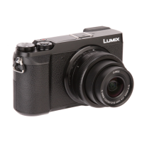
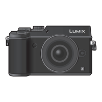
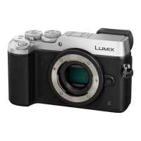
Identification and location of external controls and indicators on the camera body.
Location of controls on the top and sides of the camera body, plus lens component identification.
Explanation of the camera's ability to store and display error codes for diagnostics.
Detailed list of error codes, their meanings, and detection information for troubleshooting.
Initial inspection tips for interchangeable lenses to determine functionality and common issues.
Common issues related to focus, face detection, and exposure on the camera body.
Troubleshooting steps for flash behavior, exposure issues, and auto bracket functionality.
Guidance on addressing color reproduction problems and power-related display issues.
Information on how the optical image stabilizer functions with different lenses and modes.
Overview of the main menu categories (REC, Motion Picture, Custom, Setup, Playback) and their sub-items.
Explanation of the tilt sensor's operation and the purpose of its adjustment.
Procedure to test and confirm the functionality of the G-sensor for posture detection.
Steps for diagnosing NFC failures and verifying Wi-Fi P.C.B. operation.
List and images of specialized tools and fixtures required for camera servicing.
Guidelines for using a clean environment, especially for lens cleaning, to ensure repair quality.
Diagram showing component connection points and a list of extension cables for servicing.
A visual flowchart detailing the sequence of disassembly for the camera body components.
Diagrams illustrating the physical locations of the main printed circuit boards within the camera.
Detailed steps and screw/part references for disassembling various sections of the camera body.
Specific instructions and diagrams for removing the rear case unit, including screw details.
Procedure for safely removing the rear operation unit, including flex cable handling.
Steps for disassembling the top case unit and removing the flash P.C.B.
Detailed procedure for removing the main P.C.B., including flex cable and connector handling.
Instructions for removing the mount box unit, with important notices regarding sensitive parts.
Steps for disassembling the jack door and speaker assembly.
Procedure for removing the camera's battery unit.
Steps to remove the battery door unit and its related components.
Procedure for removing the NFC antenna unit and the SD P.C.B.
Instructions for removing the battery case and the battery out spring, with replacement notes.
Steps for removing the rear dial unit and its associated connector.
Procedure for removing the flash unit and its locking mechanisms.
Detailed steps for removing the flash assembly, including springs and levers.
Instructions for removing the LVF (Live Viewfinder) unit, including flex cable handling.
Procedure for removing the eye cup unit and the LVF panel, with handling precautions.
Steps for disassembling the LVF lens unit, including shield plates and holders.
Procedure for removing the microphone FPC unit and cover.
Reference to specific manuals for disassembling and assembling bundled lenses.
A chart detailing necessary adjustments after replacing specific camera components.
Important notes and details related to specific adjustments like AWB, G sensor, and BIS.
Information regarding the camera's compatibility and software processing for 3D interchangeable lenses.
General precautions before performing external cleaning of the camera body.
Steps for cleaning dust and dirt from the camera's outer casing.
Detailed procedure for safely cleaning dust and dirt from the camera's image sensor.
Instructions for cleaning the LVF unit, including lens surfaces.
Reference to service manuals for maintenance procedures specific to bundled lenses.
A high-level overview of the camera's main functional blocks and their interconnections.
Detailed block diagram illustrating the system control logic and component interactions.
Block diagrams detailing the video and audio processing pathways within the camera.
Block diagrams for the lens system, eye sensor, and flash circuitry.
Diagram illustrating the camera's power supply distribution and voltage regulation circuitry.
A comprehensive diagram showing the wiring connections between major internal components and external interfaces.
| Camera Type | Mirrorless |
|---|---|
| Sensor Type | Live MOS |
| Image Processor | Venus Engine |
| Lens Mount | Micro Four Thirds |
| Built-in Flash | Yes |
| Wireless Connectivity | Wi-Fi |
| Storage Media | SD/SDHC/SDXC |
| Sensor Size | 17.3 x 13.0 mm (Micro Four Thirds) |
| Sensor Resolution | 16 MP |
| Effective Pixels | 16 MP |
| ISO Sensitivity | 125-25600 |
| Image Stabilization | Sensor-shift |
| Shutter Speed | 1/8000 - 60 sec |
| Continuous Shooting | 5 fps |
| Viewfinder Type | Electronic |
| Viewfinder Resolution | 2.76 million dots |
| LCD Screen | 3.0" Tilting Touchscreen LCD, 1.04M dots |
| Video Recording | Full HD 1920 x 1080 |
| External Flash | Yes (via hot shoe) |
| Battery | DMW-BLG10 Lithium-Ion |
| Battery Life | Approx. 350 shots |