7. Remove the valve caps of both of the 2-way valve and 3-way
valve. Position both of the valves to “OPEN” using a hexagonal
wrench (4 mm).
8. Mount valve caps onto the 2-way valve and the 3-way valve.
- Be sure to check for gas leakage.
CAUTION
- If gauge needle does not move from 0
cmHg (0 MPa) to -76 cmHg (-0.1 MPa), in
step 3 above take the following measure:
- If the leak stops when the piping
connections are tightened further, continue
working from step 3.
- If the leak does not stop when the
connections are retightened, repair the
location of leak.
- Do not release refrigerant during piping
work for installation and re-installation.
Take care of the liquid refrigerant, it may
cause frostbite.
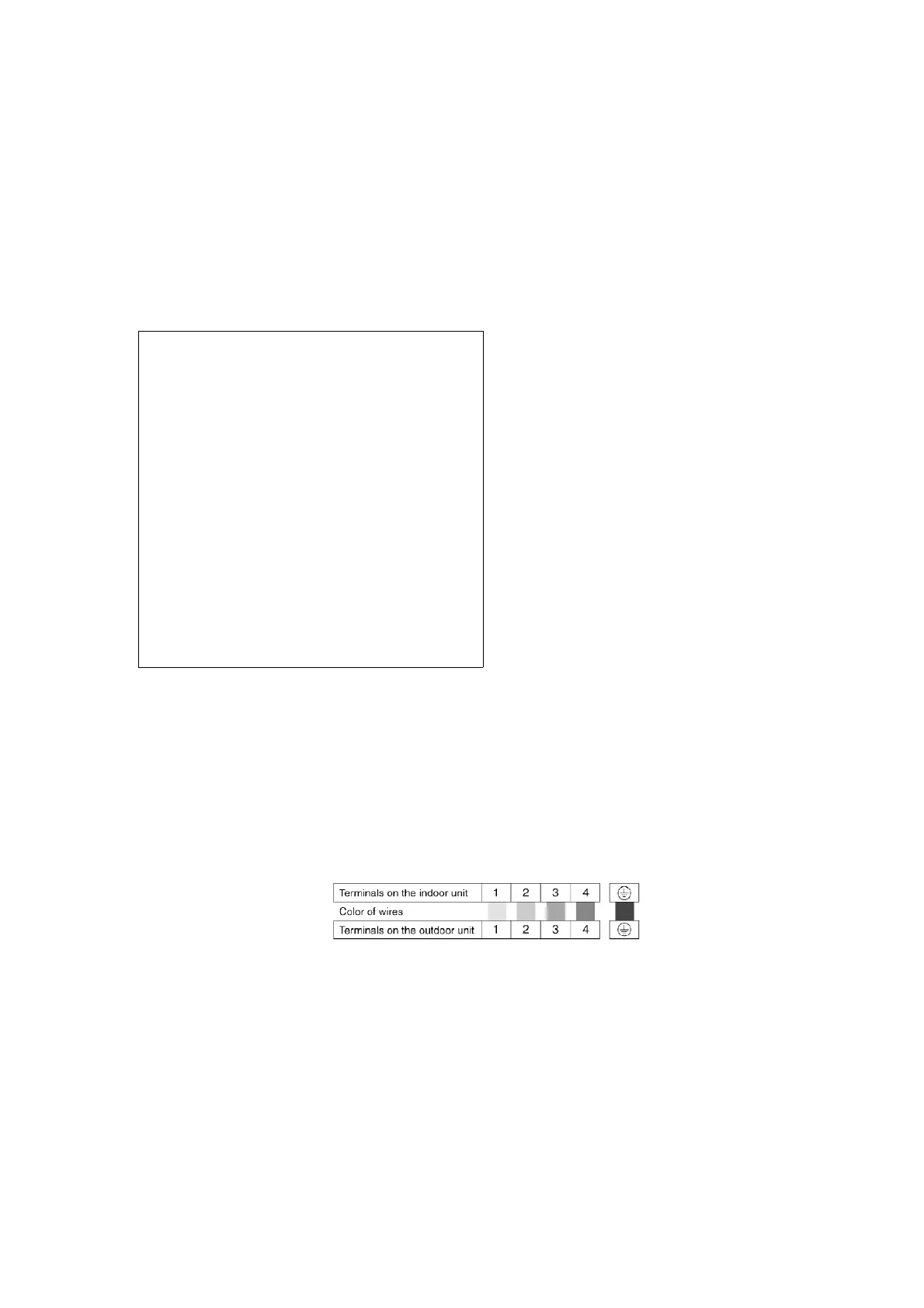
10.3.5. CONNECT THE CABLE TO THE OUTDOOR UNIT
1. Remove the control board cover from the unit by loosening the
screw.
2. Connecting cable between indoor unit and outdoor unit shall be
approved polychloroprene sheathed 5 × 1.5 mm
2
flexible cord,
type designation H05 RN-F or heavier cord.
3. Secure the cable onto the control board with the holder (clamper).
4. Attach the control board cover back to the original position with
the screw.
10.3.6. PIPE INSULATION
1. Please carry out insulation at pipe connection portion as
mentioned in Indoor/Outdoor Unit Installation Diagram. Please
57